Arduino UNO-Based Environmental Monitoring System with CO2 and Temperature Sensors
Circuit Documentation
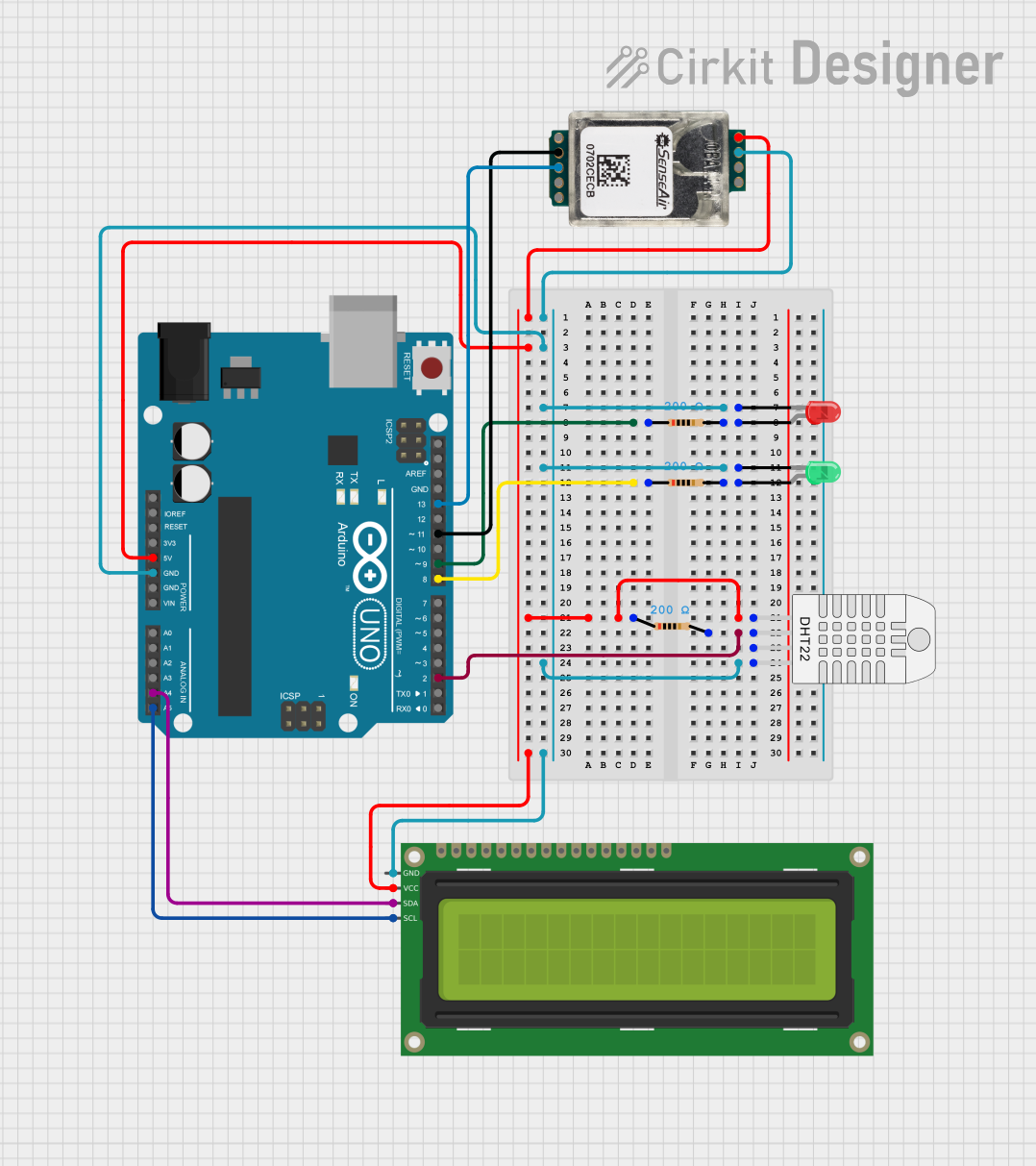
Summary
This circuit involves an Arduino UNO microcontroller interfacing with various components including LEDs, a 16x2 I2C LCD, a DHT22 temperature and humidity sensor, a SenseAir S8 CO2 sensor, and several resistors. The circuit is designed to demonstrate basic sensor readings and display functionalities.
Component List
LED: Two Pin (red)
- Description: A red LED with two pins: cathode and anode.
- Pins: cathode, anode
LED: Two Pin (green)
- Description: A green LED with two pins: cathode and anode.
- Pins: cathode, anode
16x2 I2C LCD
- Description: A 16x2 character LCD with I2C interface.
- Pins: GND, VCC, SDA, SCL
Resistor (200 Ohms)
- Description: A resistor with a resistance of 200 Ohms.
- Pins: pin1, pin2
- Properties: Resistance: 200 Ohms
Arduino UNO
- Description: A microcontroller board based on the ATmega328P.
- Pins: UNUSED, IOREF, Reset, 3.3V, 5V, GND, Vin, A0, A1, A2, A3, A4, A5, SCL, SDA, AREF, D13, D12, D11, D10, D9, D8, D7, D6, D5, D4, D3, D2, D1, D0
DHT22 (Wokwi Compatible)
- Description: A digital temperature and humidity sensor.
- Pins: VCC, SDA, NC, GND
SenseAir S8 CO2 Sensor
- Description: A CO2 sensor with multiple pins for various functionalities.
- Pins: G+, G0, Alarm OC, PWM 1kHz, DVCC out, RX, TX, R/T, CAL
Wiring Details
LED: Two Pin (red)
- cathode is connected to:
- GND of Arduino UNO
- GND of DHT22
- GND of SenseAir S8 CO2 Sensor
- GND of 16x2 I2C LCD
- cathode of LED: Two Pin (green)
- anode is connected to pin2 of a 200 Ohm resistor
LED: Two Pin (green)
- cathode is connected to:
- GND of Arduino UNO
- GND of DHT22
- GND of SenseAir S8 CO2 Sensor
- GND of 16x2 I2C LCD
- cathode of LED: Two Pin (red)
- anode is connected to pin2 of a 200 Ohm resistor
16x2 I2C LCD
- GND is connected to:
- GND of Arduino UNO
- GND of DHT22
- GND of SenseAir S8 CO2 Sensor
- cathode of LED: Two Pin (red)
- cathode of LED: Two Pin (green)
- VCC is connected to:
- 5V of Arduino UNO
- VCC of DHT22
- G+ of SenseAir S8 CO2 Sensor
- SDA is connected to A4 of Arduino UNO
- SCL is connected to A5 of Arduino UNO
Resistor (200 Ohms)
pin1 of the first resistor is connected to D9 of Arduino UNO
pin2 of the first resistor is connected to anode of LED: Two Pin (red)
pin1 of the second resistor is connected to D8 of Arduino UNO
pin2 of the second resistor is connected to anode of LED: Two Pin (green)
pin1 of the third resistor is connected to 5V of Arduino UNO
pin2 of the third resistor is connected to SDA of DHT22 and D2 of Arduino UNO
Arduino UNO
- GND is connected to:
- GND of 16x2 I2C LCD
- GND of DHT22
- GND of SenseAir S8 CO2 Sensor
- cathode of LED: Two Pin (red)
- cathode of LED: Two Pin (green)
- 5V is connected to:
- VCC of 16x2 I2C LCD
- VCC of DHT22
- G+ of SenseAir S8 CO2 Sensor
- D9 is connected to pin1 of the first 200 Ohm resistor
- D8 is connected to pin1 of the second 200 Ohm resistor
- D2 is connected to pin2 of the third 200 Ohm resistor
- A4 is connected to SDA of 16x2 I2C LCD
- A5 is connected to SCL of 16x2 I2C LCD
- D13 is connected to TX of SenseAir S8 CO2 Sensor
- D11 is connected to RX of SenseAir S8 CO2 Sensor
DHT22 (Wokwi Compatible)
- GND is connected to:
- GND of Arduino UNO
- GND of 16x2 I2C LCD
- GND of SenseAir S8 CO2 Sensor
- cathode of LED: Two Pin (red)
- cathode of LED: Two Pin (green)
- VCC is connected to:
- 5V of Arduino UNO
- VCC of 16x2 I2C LCD
- G+ of SenseAir S8 CO2 Sensor
- SDA is connected to pin2 of the third 200 Ohm resistor
SenseAir S8 CO2 Sensor
- G0 is connected to:
- GND of Arduino UNO
- GND of 16x2 I2C LCD
- GND of DHT22
- cathode of LED: Two Pin (red)
- cathode of LED: Two Pin (green)
- G+ is connected to:
- 5V of Arduino UNO
- VCC of 16x2 I2C LCD
- VCC of DHT22
- TX is connected to D13 of Arduino UNO
- RX is connected to D11 of Arduino UNO
Documented Code
Arduino UNO Code
void setup() {
  // put your setup code here, to run once:

}

void loop() {
  // put your main code here, to run repeatedly:

}
This code is a basic template for the Arduino UNO. The setup() function is where you initialize your components and settings, and the loop() function is where the main logic of your program runs repeatedly.