
Arduino Mega 2560-Based Water Level Monitoring System with LED Indicators and LCD Display
View and Edit Project In Cirkit Designer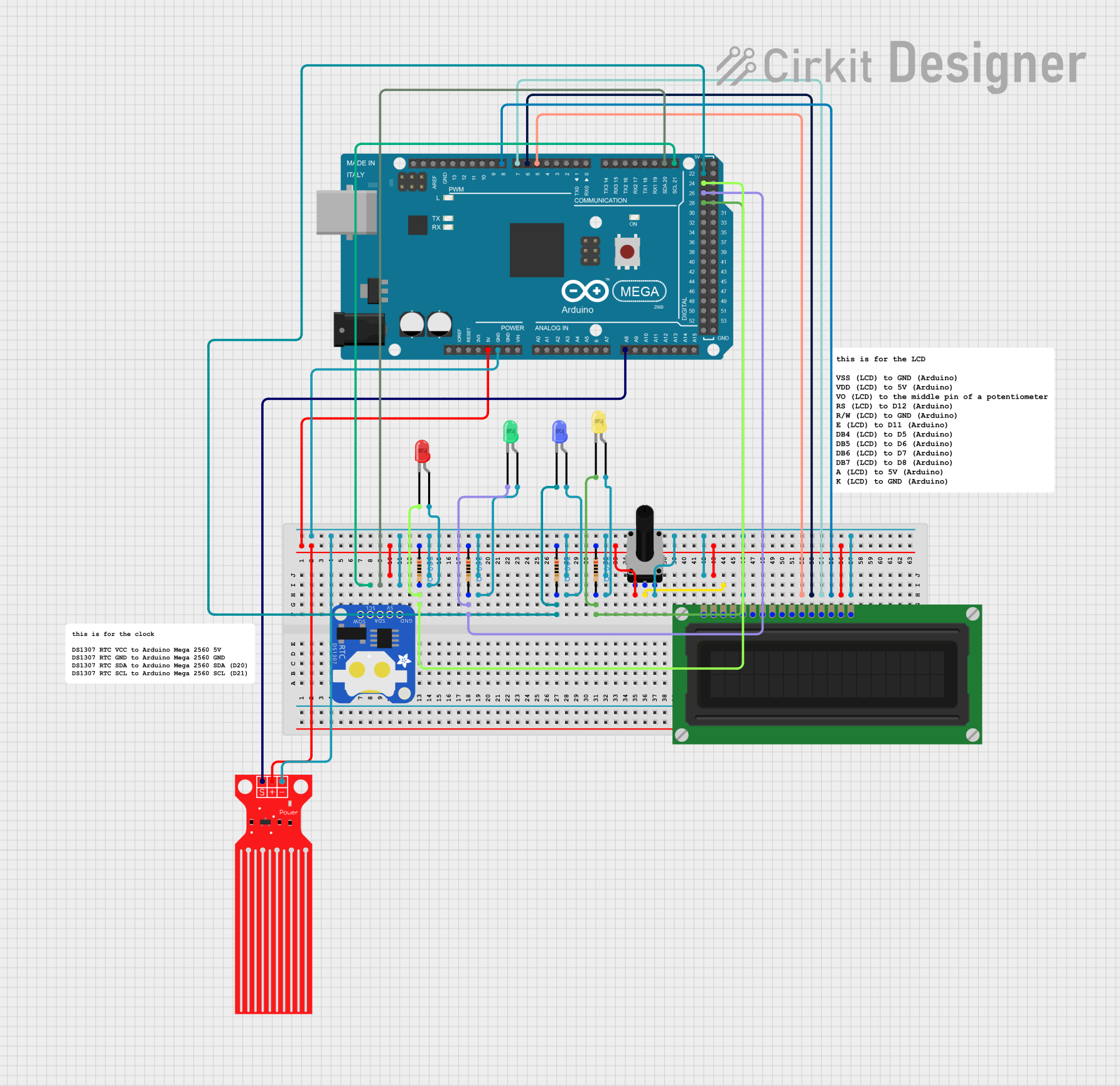
Circuit Documentation
Summary
This circuit involves an Arduino Mega 2560 microcontroller interfacing with various components including a DS1307 RTC, an LCD display, a water level sensor, multiple LEDs, resistors, and a rotary potentiometer. The circuit is designed to read water levels, display information on an LCD, and indicate statuses using LEDs.
Component List
Arduino Mega 2560
- Description: A microcontroller board based on the ATmega2560.
- Pins: IOREF, RESET, 3V3, 5V, GND, VIN, A0-A15, D0-D53, PWM pins, AREF, SDA, SCL.
Water Level Sensor
- Description: A sensor to measure the water level.
- Pins: SIG, VCC, GND.
LED: Two Pin (red)
- Description: A red LED.
- Pins: Cathode, Anode.
LED: Two Pin (green)
- Description: A green LED.
- Pins: Cathode, Anode.
LED: Two Pin (blue)
- Description: A blue LED.
- Pins: Cathode, Anode.
LED: Two Pin (yellow)
- Description: A yellow LED.
- Pins: Cathode, Anode.
Resistor (200 Ohms)
- Description: A resistor with a resistance of 200 Ohms.
- Pins: Pin1, Pin2.
DS1307 RTC (Wokwi Compatible)
- Description: A real-time clock module.
- Pins: GND, 5V, SDA, SCL, SQW.
LCD Display (16 pin)
- Description: A 16-pin LCD display.
- Pins: VSS, VDD, VO, RS, R_W, E, DB0-DB7, A, K.
Rotary Potentiometer (10k Ohms)
- Description: A rotary potentiometer with a resistance of 10k Ohms.
- Pins: Leg1, Wiper, Leg2.
Wiring Details
Arduino Mega 2560
5V connected to:
- DS1307 RTC (5V)
- Resistor (Pin1)
- Rotary Potentiometer (Leg1)
- LCD Display (VDD, A)
- Water Level Sensor (VCC)
GND connected to:
- DS1307 RTC (GND)
- Red LED (Anode)
- Green LED (Anode)
- Blue LED (Anode)
- Yellow LED (Anode)
- Rotary Potentiometer (Leg2)
- LCD Display (VSS, R_W, K)
- Water Level Sensor (GND)
D21/SCL connected to DS1307 RTC (SCL)
D20/SDA connected to DS1307 RTC (SDA)
D24 connected to:
- Resistor (Pin2)
- Red LED (Cathode)
D26 connected to:
- Resistor (Pin2)
- Green LED (Cathode)
D22 connected to:
- Resistor (Pin2)
- Blue LED (Cathode)
D28 connected to:
- Resistor (Pin2)
- Yellow LED (Cathode)
A8 connected to Water Level Sensor (SIG)
D5 PWM connected to LCD Display (DB4)
D6 PWM connected to LCD Display (DB5)
D7 PWM connected to LCD Display (DB6)
D8 PWM connected to LCD Display (DB7)
DS1307 RTC (Wokwi Compatible)
- 5V connected to Arduino Mega 2560 (5V)
- GND connected to Arduino Mega 2560 (GND)
- SCL connected to Arduino Mega 2560 (D21/SCL)
- SDA connected to Arduino Mega 2560 (D20/SDA)
Water Level Sensor
- VCC connected to Arduino Mega 2560 (5V)
- GND connected to Arduino Mega 2560 (GND)
- SIG connected to Arduino Mega 2560 (A8)
LED: Two Pin (red)
- Anode connected to Arduino Mega 2560 (GND)
- Cathode connected to Resistor (Pin2) and Arduino Mega 2560 (D24)
LED: Two Pin (green)
- Anode connected to Arduino Mega 2560 (GND)
- Cathode connected to Resistor (Pin2) and Arduino Mega 2560 (D26)
LED: Two Pin (blue)
- Anode connected to Arduino Mega 2560 (GND)
- Cathode connected to Resistor (Pin2) and Arduino Mega 2560 (D22)
LED: Two Pin (yellow)
- Anode connected to Arduino Mega 2560 (GND)
- Cathode connected to Resistor (Pin2) and Arduino Mega 2560 (D28)
Resistor (200 Ohms)
- Pin1 connected to Arduino Mega 2560 (5V)
- Pin2 connected to:
- Red LED (Cathode) and Arduino Mega 2560 (D24)
- Green LED (Cathode) and Arduino Mega 2560 (D26)
- Blue LED (Cathode) and Arduino Mega 2560 (D22)
- Yellow LED (Cathode) and Arduino Mega 2560 (D28)
LCD Display (16 pin)
- VSS connected to Arduino Mega 2560 (GND)
- VDD connected to Arduino Mega 2560 (5V)
- VO connected to Rotary Potentiometer (Wiper)
- R_W connected to Arduino Mega 2560 (GND)
- DB4 connected to Arduino Mega 2560 (D5 PWM)
- DB5 connected to Arduino Mega 2560 (D6 PWM)
- DB6 connected to Arduino Mega 2560 (D7 PWM)
- DB7 connected to Arduino Mega 2560 (D8 PWM)
- A connected to Arduino Mega 2560 (5V)
- K connected to Arduino Mega 2560 (GND)
Rotary Potentiometer (10k Ohms)
- Leg1 connected to Arduino Mega 2560 (5V)
- Leg2 connected to Arduino Mega 2560 (GND)
- Wiper connected to LCD Display (VO)
Documented Code
Arduino Mega 2560 Code
void setup() {
  // put your setup code here, to run once:

}

void loop() {
  // put your main code here, to run repeatedly:

}
This code is a basic template for the Arduino Mega 2560. The setup() function is used to initialize any settings or configurations, and the loop() function contains the main code that runs repeatedly.