
Arduino UNO-Based Smart Door System with GSM and Ultrasonic Sensor
View and Edit Project In Cirkit Designer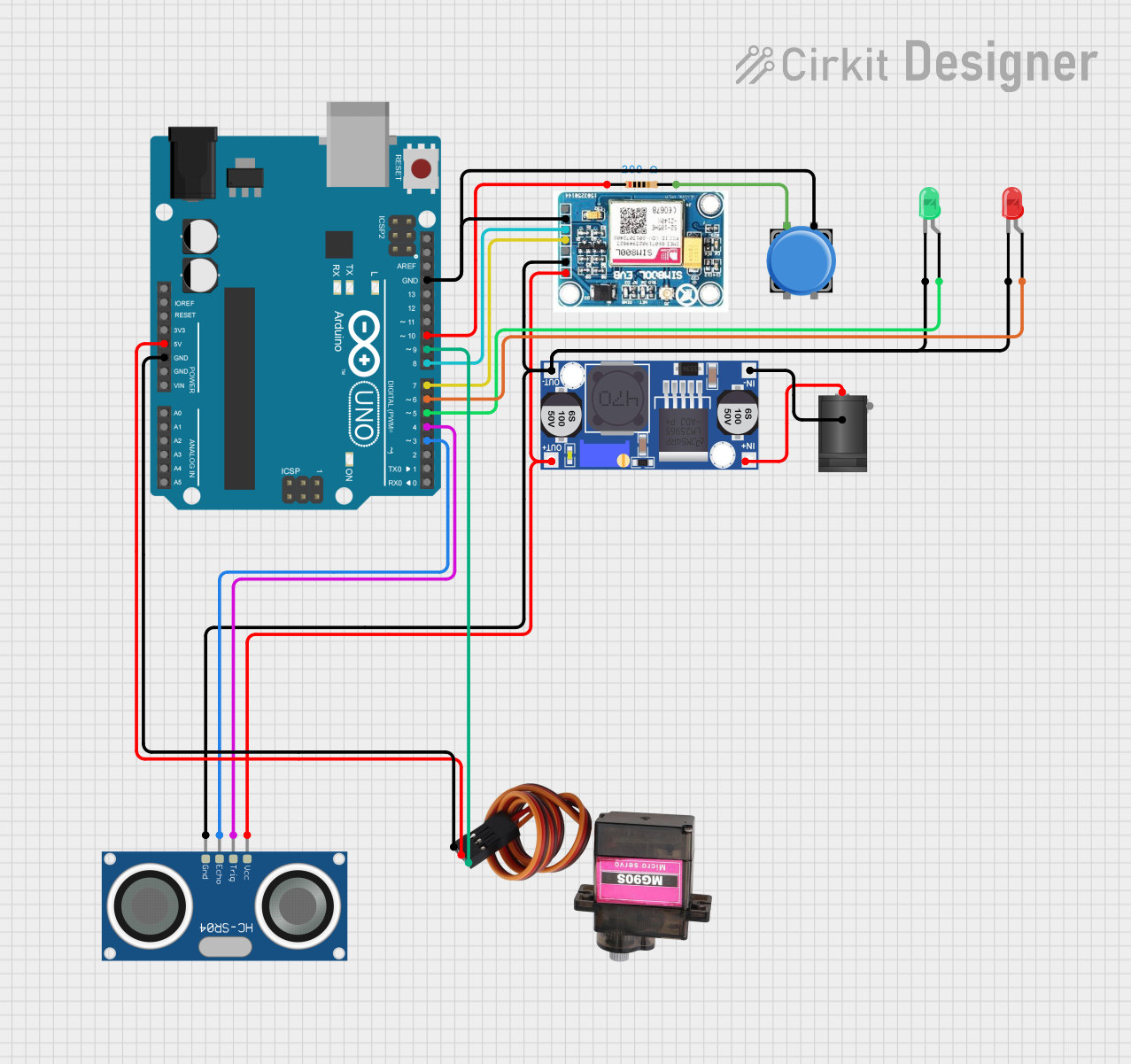
Circuit Documentation
Summary
This circuit is designed to control a door using an Arduino UNO, an MG90S servo motor, an HC-SR04 ultrasonic sensor, a SIM 800L GSM module, and various other components. The system can open and close the door based on button presses, ultrasonic sensor readings, and GSM commands. It also sends SMS notifications when someone is detected at the door.
Component List
Arduino UNO
- Description: Microcontroller board based on the ATmega328P.
- Pins: UNUSED, IOREF, Reset, 3.3V, 5V, GND, Vin, A0, A1, A2, A3, A4, A5, SCL, SDA, AREF, D13, D12, D11, D10, D9, D8, D7, D6, D5, D4, D3, D2, D1, D0
HC-SR04 Ultrasonic Sensor
- Description: Ultrasonic distance sensor.
- Pins: VCC, TRIG, ECHO, GND
MG90S Servo Motor
- Description: Micro servo motor.
- Pins: SIG, VCC, GND
SIM 800L V2.0 GSM Module
- Description: GSM module for sending and receiving SMS.
- Pins: SIM_TXD, VDD, SIM.RXD, 5V/4V, GND, RST
Buck Converter
- Description: DC-DC step-down converter.
- Pins: IN+, IN-, OUT+, OUT-
2.1mm DC Barrel Jack
- Description: Power connector.
- Pins: switch, sleeve, center
Pushbutton
- Description: Momentary pushbutton switch.
- Pins: Pin 2, Pin 1, Pin 3, Pin 4
LED: Two Pin (red)
- Description: Red LED.
- Pins: cathode, anode
LED: Two Pin (green)
- Description: Green LED.
- Pins: cathode, anode
Resistor
- Description: 200 Ohm resistor.
- Pins: pin1, pin2
- Properties: Resistance = 200 Ohms
Wiring Details
Arduino UNO
- 5V to MG90S VCC
- GND to MG90S GND, SIM 800L V2.0 GSM GND, Pushbutton Pin 3
- D10 to Resistor pin1
- D9 to MG90S SIG
- D8 to SIM 800L V2.0 GSM SIM.RXD
- D7 to SIM 800L V2.0 GSM SIM_TXD
- D6 to LED: Two Pin (red) anode
- D5 to LED: Two Pin (green) anode
- D4 to HC-SR04 Ultrasonic Sensor TRIG
- D3 to HC-SR04 Ultrasonic Sensor ECHO
HC-SR04 Ultrasonic Sensor
- VCC to Buck converter OUT+
- GND to Buck converter OUT-
MG90S Servo Motor
- VCC to Arduino UNO 5V
- GND to Arduino UNO GND
- SIG to Arduino UNO D9
SIM 800L V2.0 GSM Module
- GND to Arduino UNO GND, Buck converter OUT-
- SIM.RXD to Arduino UNO D8
- SIM_TXD to Arduino UNO D7
- 5V/4V to Buck converter OUT+
Buck Converter
- OUT+ to SIM 800L V2.0 GSM 5V/4V, HC-SR04 Ultrasonic Sensor VCC
- OUT- to SIM 800L V2.0 GSM GND, HC-SR04 Ultrasonic Sensor GND, LED: Two Pin (green) cathode, LED: Two Pin (red) cathode
- IN+ to 2.1mm DC Barrel Jack center
- IN- to 2.1mm DC Barrel Jack switch
2.1mm DC Barrel Jack
- center to Buck converter IN+
- switch to Buck converter IN-
Pushbutton
- Pin 3 to Arduino UNO GND
- Pin 1 to Resistor pin2
LED: Two Pin (red)
- anode to Arduino UNO D6
- cathode to Buck converter OUT-
LED: Two Pin (green)
- anode to Arduino UNO D5
- cathode to Buck converter OUT-
Resistor
- pin1 to Arduino UNO D10
- pin2 to Pushbutton Pin 1
Code Documentation
#include <Servo.h>
#include <SoftwareSerial.h>

// Pin definitions
const int trigPin = 4;
const int echoPin = 3;
const int greenLEDPin = 5;
const int redLEDPin = 6;
const int buttonPin = 10;
const int servoPin = 9;
const int gsmTXPin = 7;
const int gsmRXPin = 8;

Servo doorServo;
SoftwareSerial gsmSerial(gsmTXPin, gsmRXPin);

const char allowedPhoneNumber[] = "+254701568555";
const long detectionRange = 400; // 4 meters in centimeters

void setup() {
  // Initialize serial communication
  Serial.begin(9600);
  gsmSerial.begin(9600);

  // Initialize pins
  pinMode(trigPin, OUTPUT);
  pinMode(echoPin, INPUT);
  pinMode(greenLEDPin, OUTPUT);
  pinMode(redLEDPin, OUTPUT);
  pinMode(buttonPin, INPUT_PULLUP); // Use internal pull-up resistor

  // Attach the servo motor
  doorServo.attach(servoPin);

  // Initialize the door to closed position
  closeDoor();

  // Initialize GSM module
  initializeGSM();
}

void loop() {
  // Check for button press
  if (digitalRead(buttonPin) == LOW) { // Adjust for pull-up resistor
    toggleDoor();
    delay(1000); // Debounce delay
  }

  // Check for GSM command
  if (gsmSerial.available() > 0) {
    handleGSM();
  }

  // Check for ultrasonic sensor trigger
  long distance = measureDistance();
  if (distance > 0 && distance <= detectionRange) {
    sendSMS(allowedPhoneNumber, "Someone is at the door");
    delay(10000); // Wait 10 seconds before checking again to avoid spamming
  }
}

void openDoor() {
  doorServo.write(90); // Rotate servo to 90 degrees
  digitalWrite(greenLEDPin, HIGH); // Turn on green LED
  digitalWrite(redLEDPin, LOW); // Turn off red LED
}

void closeDoor() {
  doorServo.write(0); // Rotate servo to 0 degrees
  digitalWrite(greenLEDPin, LOW); // Turn off green LED
  digitalWrite(redLEDPin, HIGH); // Turn on red LED
}

void toggleDoor() {
  static bool doorOpen = false;
  if (doorOpen) {
    closeDoor();
  } else {
    openDoor();
    sendSMS(allowedPhoneNumber, "The door has been opened manually with button");
  }
  doorOpen = !doorOpen;
}

void initializeGSM() {
  delay(1000); // Give time for GSM module to initialize
  gsmSerial.println("AT"); // Check if the module is ready
  delay(1000);
  gsmSerial.println("AT+CMGF=1"); // Set SMS to text mode
  delay(1000);
  gsmSerial.println("AT+CNMI=1,2,0,0,0"); // Configure the module to send SMS data to the serial port
  delay(1000);
}

void handleGSM() {
  if (gsmSerial.find("+CMT:")) {
    delay(10); // Wait for the rest of the message to arrive
    String senderNumber = gsmSerial.readStringUntil(',');
    senderNumber.trim();
    senderNumber.remove(0, 1); // Remove the leading "
    senderNumber.remove(senderNumber.length() - 1); // Remove the trailing "

    if (senderNumber == allowedPhoneNumber) {
      String message = gsmSerial.readStringUntil('\n');
      message.trim();
      if (message.equalsIgnoreCase("Open")) {
        openDoor();
      }
    }
  }
}

void sendSMS(const char* phoneNumber, const char* message) {
  gsmSerial.print("AT+CMGS=\"");
  gsmSerial.print(phoneNumber);
  gsmSerial.println("\"");
  delay(100); // Wait for the prompt
  gsmSerial.print(message);
  delay(100); // Wait for the message to be sent
  gsmSerial.write