Arduino UNO R4 WiFi-Controlled Thermal Imaging Camera with TFT Display
Circuit Documentation
Summary
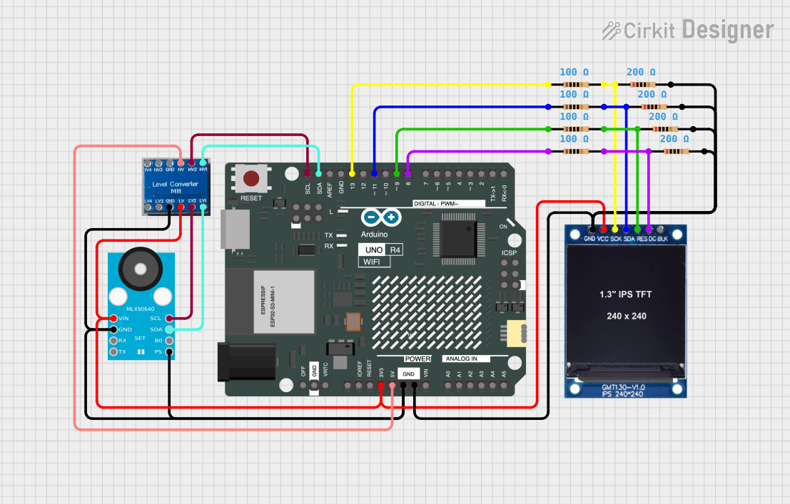
This circuit integrates an Arduino UNO R4 WiFi with a 1.3 inch TFT Module 240×240 ST7789 display, a GY-MCU90640 thermal camera module, and a HiLetGo Level Shifter for voltage level translation. The circuit also includes multiple resistors for current limiting and signal conditioning. The Arduino UNO R4 WiFi serves as the central processing unit, interfacing with the display and thermal camera module to process and visualize thermal data.
Component List
Arduino UNO R4 WiFi
- Description: A microcontroller board based on the ATmega328P with integrated WiFi capability.
- Pins: OFF, GND, VRTC, IIC0_SCL, IIC0_SDA, 3V3, GPIO 41, GPIO 0, GPIO 42, GPIO 43, GPIO 44, BOOT, IOREF, RESET, 5V, VIN, A0, A1, A2, A3, A4, A5, RSPCKA, CIPO, COPI, D0/RX, D1/TX, D2, D3, D4, D5, D6, D7, D8, D9, D10, D11, D12, D13, AREF, SDA, SCL.
HiLetGo Level Shifter
- Description: A device that shifts the voltage levels of signals to match different logic levels between devices.
- Pins: LV4, LV3, GND, LV, LV2, HV4, HV3, HV, HV2, LV1, HV1.
Resistor (100 Ohms)
- Description: A passive two-terminal electrical component that implements electrical resistance as a circuit element.
- Quantity: 4
Resistor (200 Ohms)
- Description: A passive two-terminal electrical component that implements electrical resistance as a circuit element.
- Quantity: 4
1.3 inch TFT Module 240×240 ST7789
- Description: A small LCD display with a resolution of 240x240 pixels, capable of displaying full-color graphics.
- Pins: GND, VCC, SCK, SDA, RES, DC, BLK.
GY-MCU90640
- Description: A thermal camera module that captures infrared radiation as heat and represents it as temperature data.
- Pins: Pin 1, Pin 2, Pin 3, Pin 4, Pin 5, Pin 6, Pin 7, Pin 8.
Wiring Details
Arduino UNO R4 WiFi
- 3V3: Connected to HiLetGo Level Shifter LV, 1.3 inch TFT Module VCC, GY-MCU90640 Pin 1.
- 5V: Connected to HiLetGo Level Shifter HV.
- GND: Connected to HiLetGo Level Shifter GND, GY-MCU90640 Pin 2 and Pin 5, 1.3 inch TFT Module GND, and all GND pins of the resistors.
- D8: Connected to a 100 Ohm resistor.
- D9: Connected to a 100 Ohm resistor.
- D11: Connected to a 100 Ohm resistor.
- D13: Connected to a 100 Ohm resistor.
- SDA: Connected to HiLetGo Level Shifter HV1.
- SCL: Connected to HiLetGo Level Shifter HV2.
HiLetGo Level Shifter
- LV: Connected to Arduino UNO R4 WiFi 3V3.
- HV: Connected to Arduino UNO R4 WiFi 5V.
- GND: Connected to Arduino UNO R4 WiFi GND.
- LV1: Connected to GY-MCU90640 Pin 7.
- LV2: Connected to GY-MCU90640 Pin 8.
- HV1: Connected to Arduino UNO R4 WiFi SDA.
- HV2: Connected to Arduino UNO R4 WiFi SCL.
1.3 inch TFT Module 240×240 ST7789
- VCC: Connected to Arduino UNO R4 WiFi 3V3.
- GND: Connected to Arduino UNO R4 WiFi GND through a 200 Ohm resistor.
- SCK: Connected to Arduino UNO R4 WiFi D13 through a 100 Ohm resistor.
- SDA: Connected to Arduino UNO R4 WiFi D11 through a 100 Ohm resistor.
- RES: Connected to Arduino UNO R4 WiFi D9 through a 100 Ohm resistor.
- DC: Connected to Arduino UNO R4 WiFi D8 through a 100 Ohm resistor.
GY-MCU90640
- Pin 1: Connected to Arduino UNO R4 WiFi 3V3.
- Pin 2 and Pin 5: Connected to Arduino UNO R4 WiFi GND.
- Pin 7: Connected to HiLetGo Level Shifter LV1.
- Pin 8: Connected to HiLetGo Level Shifter LV2.
Documented Code
The code provided is for the Arduino UNO R4 WiFi microcontroller. It includes libraries for the Adafruit MLX90640 thermal camera and the Adafruit ST7789 TFT display, as well as the SPI library for serial communication. The code initializes the display and the thermal camera, then enters a loop where it reads temperature data from the thermal camera and displays it on the TFT screen. The display shows a color-mapped thermal image and updates the ambient temperature and frame rate (FPS) on the screen.
#include <Adafruit_MLX90640.h>
#include <Adafruit_GFX.h>    // Core graphics library
#include <Adafruit_ST7789.h> // Hardware-specific library for ST7789
#include <SPI.h>

// ... (Code omitted for brevity)

void setup() {
  // ... (Setup code omitted for brevity)
}

void loop() {
  // ... (Loop code omitted for brevity)
}
Note: The full code is not displayed here due to brevity. The provided code snippet shows the inclusion of necessary libraries and the structure of the setup() and loop() functions. The actual code includes detailed implementation for initializing the hardware components, capturing thermal data, processing it, and displaying it on the TFT screen.