
Arduino UNO Based Traffic Light Control System with GPS and GSM Integration
View and Edit Project In Cirkit Designer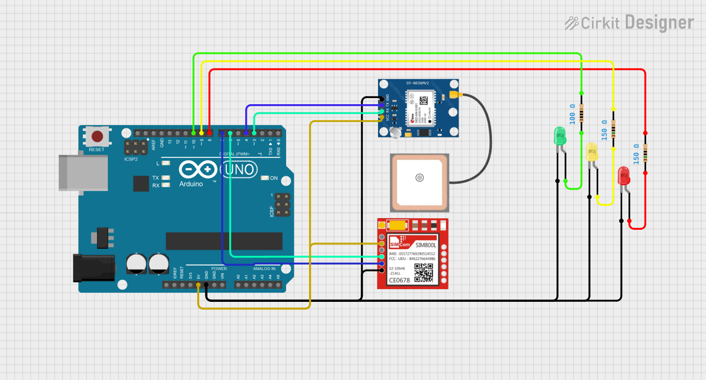
Circuit Documentation
Summary
This circuit is designed to control a traffic light system with an Arduino UNO microcontroller at its core. It interfaces with a GPS module (GPS NEO 6M) and a GSM module (Sim800l) to receive the location of an ambulance and control the traffic lights accordingly. The traffic lights are represented by three LEDs (red, yellow, and green), each with a corresponding resistor to limit the current. The Arduino UNO controls the LEDs based on the ambulance's proximity to the traffic light and sends a message to the ambulance using the GSM module when the light is green.
Component List
Arduino UNO
- Microcontroller board based on the ATmega328P
- Digital I/O Pins: 14 (of which 6 provide PWM output)
- Analog Input Pins: 6
- Operating Voltage: 5V
GPS NEO 6M
- GPS module for satellite navigation
- Operating Voltage: 3.3V - 5V
Sim800l
- GSM/GPRS module for cellular communication
- Operating Voltage: 3.4V - 4.4V
LED: Two Pin (red)
- Red indicator LED
- Forward Voltage: ~2V
LED: Two Pin (green)
- Green indicator LED
- Forward Voltage: ~2V
LED: Two Pin (yellow)
- Yellow indicator LED
- Forward Voltage: ~2V
Resistor (150 Ohms)
- Resistor with 150 Ohms resistance
- Used to limit current through LEDs
Resistor (100 Ohms)
- Resistor with 100 Ohms resistance
- Used to limit current through LEDs
Wiring Details
Arduino UNO
5Vconnected to VCC of GPS NEO 6M and Sim800lGNDconnected to GND of GPS NEO 6M, Sim800l, and cathodes of all LEDsD10connected to one end of 100 Ohm resistorD9connected to one end of 150 Ohm resistor (for yellow LED)D8connected to one end of 150 Ohm resistor (for red LED)D7connected to TXD of Sim800lD6connected to RXD of Sim800lD4connected to TX of GPS NEO 6MD3connected to RX of GPS NEO 6M
GPS NEO 6M
VCCconnected to 5V of Arduino UNOGNDconnected to GND of Arduino UNOTXconnected to D4 of Arduino UNORXconnected to D3 of Arduino UNO
Sim800l
VCCconnected to 5V of Arduino UNOGNDconnected to GND of Arduino UNOTXDconnected to D7 of Arduino UNORXDconnected to D6 of Arduino UNO
LEDs (Red, Yellow, Green)
cathodeconnected to GND of Arduino UNOanodeof red LED connected to other end of 150 Ohm resistoranodeof yellow LED connected to other end of 150 Ohm resistoranodeof green LED connected to other end of 100 Ohm resistor
Resistor (150 Ohms)
- One end connected to D9 (yellow LED) and D8 (red LED) of Arduino UNO
- Other end connected to anode of yellow LED and anode of red LED
Resistor (100 Ohms)
- One end connected to D10 of Arduino UNO
- Other end connected to anode of green LED
Documented Code
#include <SoftwareSerial.h>

// Pins for GPS and GSM
SoftwareSerial gpsSerial(4, 3);  // RX, TX for GPS
SoftwareSerial gsmSerial(7, 6);  // RX, TX for GSM

// Traffic light LEDs
int redLED = 8;
int yellowLED = 9;
int greenLED = 10;

// Variables for GPS
String ambulanceLatitude, ambulanceLongitude;
float distanceThreshold = 100.0;  // Distance in meters

// Function to calculate distance (replace with your formula if necessary)
float calculateDistance(float lat1, float lon1, float lat2, float lon2) {
  // Use Haversine formula to calculate distance (in meters)
  // Simplified here for brevity, can use libraries like TinyGPS
  return 0; // Replace with actual calculation
}

void setup() {
  // Initialize serial communication
  Serial.begin(9600);
  gpsSerial.begin(9600);
  gsmSerial.begin(9600);

  // Initialize traffic light pins
  pinMode(redLED, OUTPUT);
  pinMode(yellowLED, OUTPUT);
  pinMode(greenLED, OUTPUT);

  // Set initial state (Red light on)
  digitalWrite(redLED, HIGH);
  digitalWrite(yellowLED, LOW);
  digitalWrite(greenLED, LOW);
}

void loop() {
  // Get GPS data from ambulance
  if (gpsSerial.available()) {
    ambulanceLatitude = gpsSerial.readStringUntil(',');
    ambulanceLongitude = gpsSerial.readStringUntil('\n');

    // Dummy coordinates for the traffic light location
    float trafficLightLat = 30.123456;
    float trafficLightLon = 31.123456;

    // Calculate distance between ambulance and traffic light
    float distance = calculateDistance(trafficLightLat, trafficLightLon, ambulanceLatitude.toFloat(), ambulanceLongitude.toFloat());

    // Check if ambulance is within range
    if (distance < distanceThreshold) {
      // Turn Green light ON and Red light OFF
      digitalWrite(redLED, LOW);
      digitalWrite(greenLED, HIGH);

      // Send message to the ambulance
      sendMessageToAmbulance();
    } else {
      // Turn Red light ON and Green light OFF
      digitalWrite(redLED, HIGH);
      digitalWrite(greenLED, LOW);
    }
  }
}

void sendMessageToAmbulance() {
  // Send a GSM message to the ambulance indicating the green light
  gsmSerial.println("AT+CMGF=1");  // Set GSM to text mode
  delay(1000);
  gsmSerial.println("AT+CMGS=\"+123456789\"");  // Replace with ambulance phone number
  delay(1000);
  gsmSerial.println("Traffic light is green, you can pass!");  // Message
  delay(100);
  gsmSerial.write(26);  // Send CTRL+Z to end the message
  delay(1000);
}
This code is designed to run on the Arduino UNO microcontroller. It initializes two software serial ports for communication with the GPS and GSM modules, sets up the pins for the traffic light LEDs, and enters a loop where it reads GPS data to determine the ambulance's proximity to the traffic light. If the ambulance is within a certain distance, it switches the traffic light to green and sends a message to the ambulance.