Cirkit Designer
Your all-in-one circuit design IDE
Home /
Project Documentation
Arduino-Controlled Robot with Ultrasonic Sensor and Dual DC Motors
Circuit Documentation
Summary
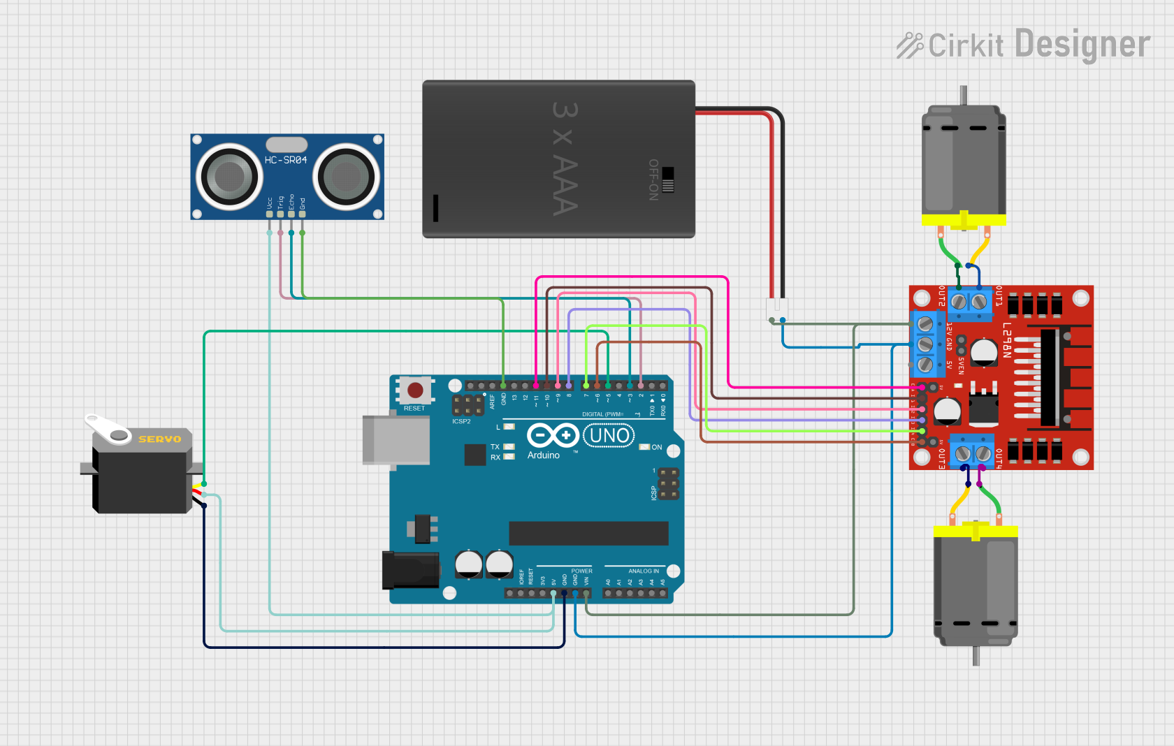
This circuit is designed to control a servo and two DC motors using an Arduino UNO microcontroller. It includes an L298N DC motor driver to manage the motors' operations and an HC-SR04 Ultrasonic Sensor for distance measurement. The circuit is powered by a 3xAAA Battery Pack with a switch and JST connector. The Arduino UNO is the central processing unit that interfaces with the motor driver, servo, and ultrasonic sensor to perform specific tasks as programmed.
Component List
Arduino UNO
- Microcontroller board based on the ATmega328P
- It has 14 digital input/output pins, 6 analog inputs, a 16 MHz quartz crystal, a USB connection, a power jack, an ICSP header, and a reset button.
DC Motor (x2)
- An electric motor that runs on direct current (DC) electricity.
- Typically used for driving mechanical loads.
Servo
- A rotary actuator or linear actuator that allows for precise control of angular or linear position, velocity, and acceleration.
- It consists of a suitable motor coupled to a sensor for position feedback.
L298N DC Motor Driver
- A high current dual full-bridge driver designed to accept standard TTL logic levels.
- It is capable of driving high voltage/high current DC motors.
HC-SR04 Ultrasonic Sensor
- An ultrasonic distance sensor that provides 2cm to 400cm of non-contact measurement functionality with a ranging accuracy that can reach up to 3mm.
3xAAA Battery Pack with Switch and JST
- A battery holder for three AAA batteries with an integrated switch and JST connector for easy power supply management.
Wiring Details
Arduino UNO
5Vconnected to Servo VCC and HC-SR04 VCCGNDconnected to Servo GND, HC-SR04 GND, and L298N GNDVinconnected to 3xAAA Battery Pack POSD11connected to L298N ENAD10connected to L298N IN1D9connected to L298N IN2D8connected to L298N IN3D7connected to L298N IN4D6connected to L298N ENBD5connected to Servo pulseD3connected to HC-SR04 ECHOD2connected to HC-SR04 TRIG
DC Motor #1
pin 1connected to L298N OUT4pin 2connected to L298N OUT3
DC Motor #2
pin 1connected to L298N OUT2pin 2connected to L298N OUT1
Servo
vccconnected to Arduino UNO 5Vgndconnected to Arduino UNO GNDpulseconnected to Arduino UNO D5
L298N DC Motor Driver
OUT1toOUT4connected to DC Motors12Vconnected to 3xAAA Battery Pack POSGNDconnected to Arduino UNO GNDENAandENBconnected to Arduino UNO D11 and D6 respectivelyIN1toIN4connected to Arduino UNO D10 to D7 respectively
HC-SR04 Ultrasonic Sensor
VCCconnected to Arduino UNO 5VGNDconnected to Arduino UNO GNDECHOconnected to Arduino UNO D3TRIGconnected to Arduino UNO D2
3xAAA Battery Pack with Switch and JST
POSconnected to Arduino UNO Vin and L298N 12VNEGconnected to Arduino UNO GND
Documented Code
Arduino UNO Code (sketch.ino)
void setup() {
  // put your setup code here, to run once:

}

void loop() {
  // put your main code here, to run repeatedly:

}
Note: The provided code is a template and does not contain any functional code. It needs to be populated with instructions to control the motors, servo, and read data from the ultrasonic sensor.