
ESP32-Controlled Automated Irrigation System with Soil Moisture Sensing
View and Edit Project In Cirkit Designer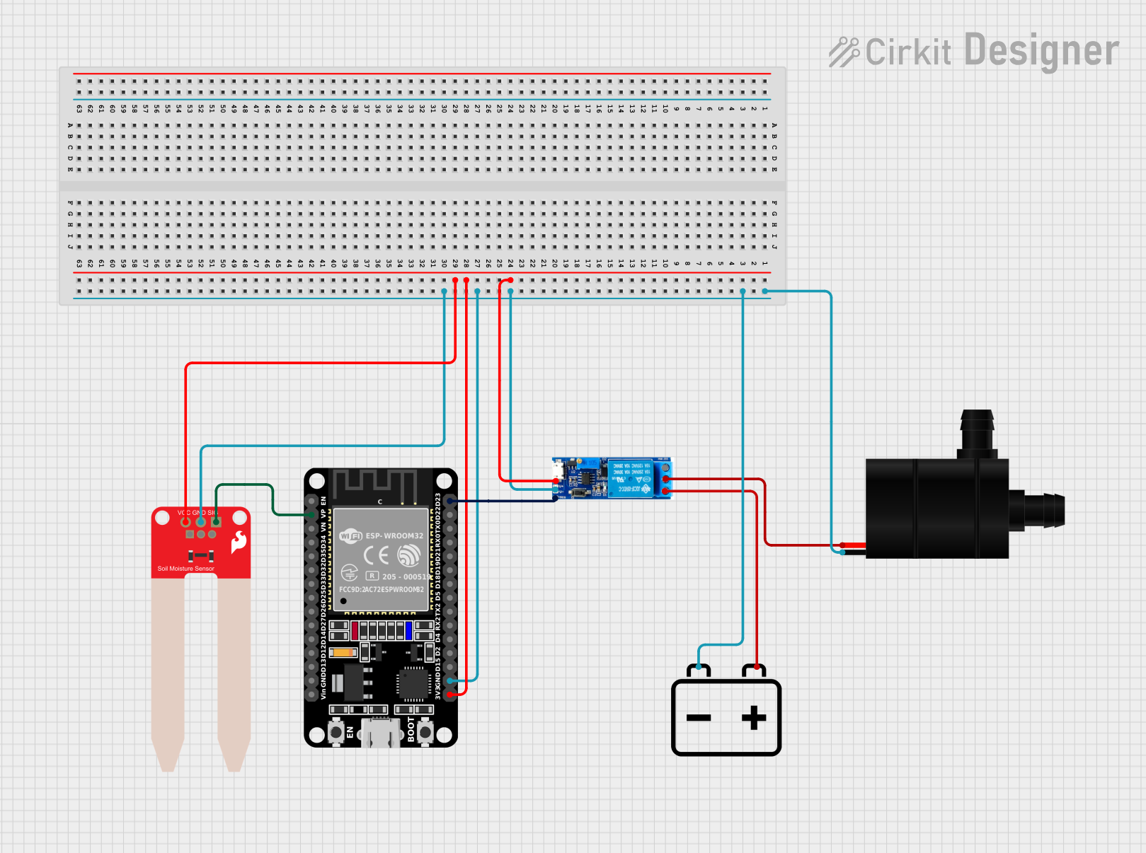
Circuit Documentation
Summary of the Circuit
This circuit is designed to control a water pump based on soil moisture levels detected by a SparkFun Soil Moisture Sensor. The core of the circuit is an ESP32 microcontroller, which reads the moisture level and controls a relay module to turn the water pump on or off. The relay module is powered by a 12v battery, which also powers the water pump. The ESP32 and the soil moisture sensor are powered by the 3.3V output from the ESP32.
Component List
ESP32 (30 pin)
- Description: A microcontroller with WiFi and Bluetooth capabilities, featuring a wide range of GPIO pins.
- Purpose: Acts as the central processing unit of the circuit, reading sensor data and controlling the relay module.
SparkFun Soil Moisture Sensor
- Description: A sensor that measures the volumetric content of water in the soil and outputs an analog signal.
- Purpose: Provides soil moisture level data to the ESP32 for processing.
Relay module 5v-30v
- Description: An electrically operated switch that allows the ESP32 to control higher power circuits, such as the water pump.
- Purpose: Enables the ESP32 to safely control the water pump.
Water Pump
- Description: A pump that moves water through a system.
- Purpose: Waters the soil when activated by the relay module.
12v Battery
- Description: A power source providing 12 volts.
- Purpose: Powers the water pump and the relay module.
Wiring Details
ESP32 (30 pin)
- GND: Connected to the ground plane of the circuit.
- 3V3: Provides power to the relay module and the soil moisture sensor.
- VP: Reads the analog signal from the soil moisture sensor.
- D23: Controls the trigger pin of the relay module.
SparkFun Soil Moisture Sensor
- VCC: Connected to the 3.3V output from the ESP32.
- GND: Connected to the ground plane of the circuit.
- SIG: Outputs an analog signal to the VP pin of the ESP32.
Relay module 5v-30v
- V+: Connected to the 3.3V output from the ESP32.
- V-: Connected to the ground plane of the circuit.
- Trigger: Controlled by the D23 pin of the ESP32.
- Common contact: Connected to the VCC of the water pump.
- Normally open: Connected to the "+" of the 12v battery.
Water Pump
- VCC: Connected to the common contact of the relay module.
- GND: Connected to the ground plane of the circuit.
12v Battery
- +: Connected to the normally open contact of the relay module.
- -: Connected to the ground plane of the circuit.
Documented Code
Since no code was provided, this section is left blank. The expected code would include initialization of the ESP32's GPIO pins, analog reading from the soil moisture sensor, and logic to control the relay module based on the moisture level.
Please note that the actual implementation of the code would be necessary to provide a complete documentation of the system's operation. The code would handle tasks such as setting up the ESP32's WiFi and Bluetooth functionalities if needed, reading the analog value from the soil moisture sensor, converting that value to a moisture level, and then using a threshold to control the relay module, which in turn controls the water pump.