
Circuit Documentation
Summary of the Circuit
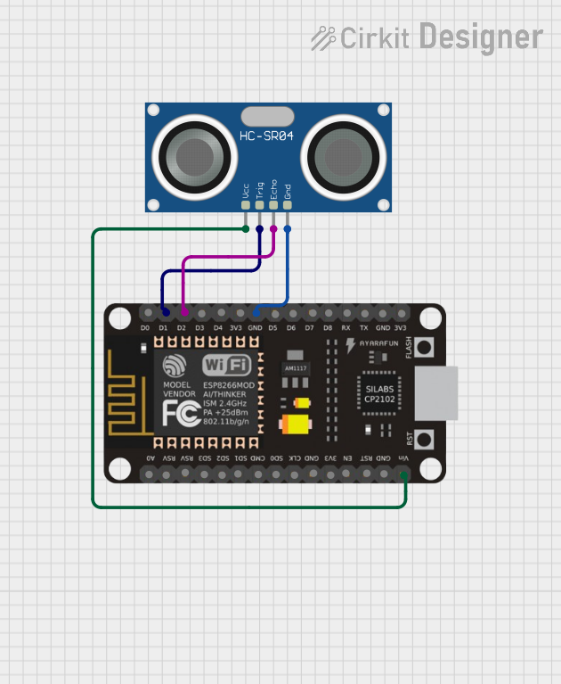
This circuit integrates an HC-SR04 Ultrasonic Sensor with an ESP8266 NodeMCU microcontroller. The purpose of the circuit is to measure distances using the ultrasonic sensor and process the data with the ESP8266 NodeMCU. The ESP8266 is responsible for triggering the sensor to send an ultrasonic pulse and then listening for the echo to determine the distance to an object.
Component List
HC-SR04 Ultrasonic Sensor
- Description: An ultrasonic ranging sensor capable of measuring distances from 2cm to 400cm.
- Pins:
- VCC: Power supply input (5V)
- TRIG: Trigger input, used to initiate the ranging
- ECHO: Echo output, where the sensor outputs the pulse indicating the range
- GND: Ground
ESP8266 NodeMCU
- Description: A Wi-Fi enabled microcontroller module with an ESP8266 chip.
- Pins:
- D0-D8: General purpose I/O pins
- RX, TX: UART communication pins
- A0: Analog input
- 3V3: 3.3V power supply output
- GND: Ground
- VIN: Power supply input (5V)
- RST, EN: Reset and enable pins
- SD0-SD3, CMD, CLK: SD card interface
- RSV: Reserved
Wiring Details
HC-SR04 Ultrasonic Sensor
- VCC connected to ESP8266 NodeMCU VIN
- TRIG connected to ESP8266 NodeMCU D1
- ECHO connected to ESP8266 NodeMCU D2
- GND connected to ESP8266 NodeMCU GND
ESP8266 NodeMCU
- VIN connected to HC-SR04 Ultrasonic Sensor VCC
- D1 connected to HC-SR04 Ultrasonic Sensor TRIG
- D2 connected to HC-SR04 Ultrasonic Sensor ECHO
- GND connected to HC-SR04 Ultrasonic Sensor GND
Documented Code
No code has been provided for the microcontroller. Typically, the code would be responsible for initializing the sensor, triggering the ultrasonic pulse, measuring the time taken for the echo to return, and calculating the distance based on the speed of sound. The code would also handle any communication or data processing tasks as required by the application.