
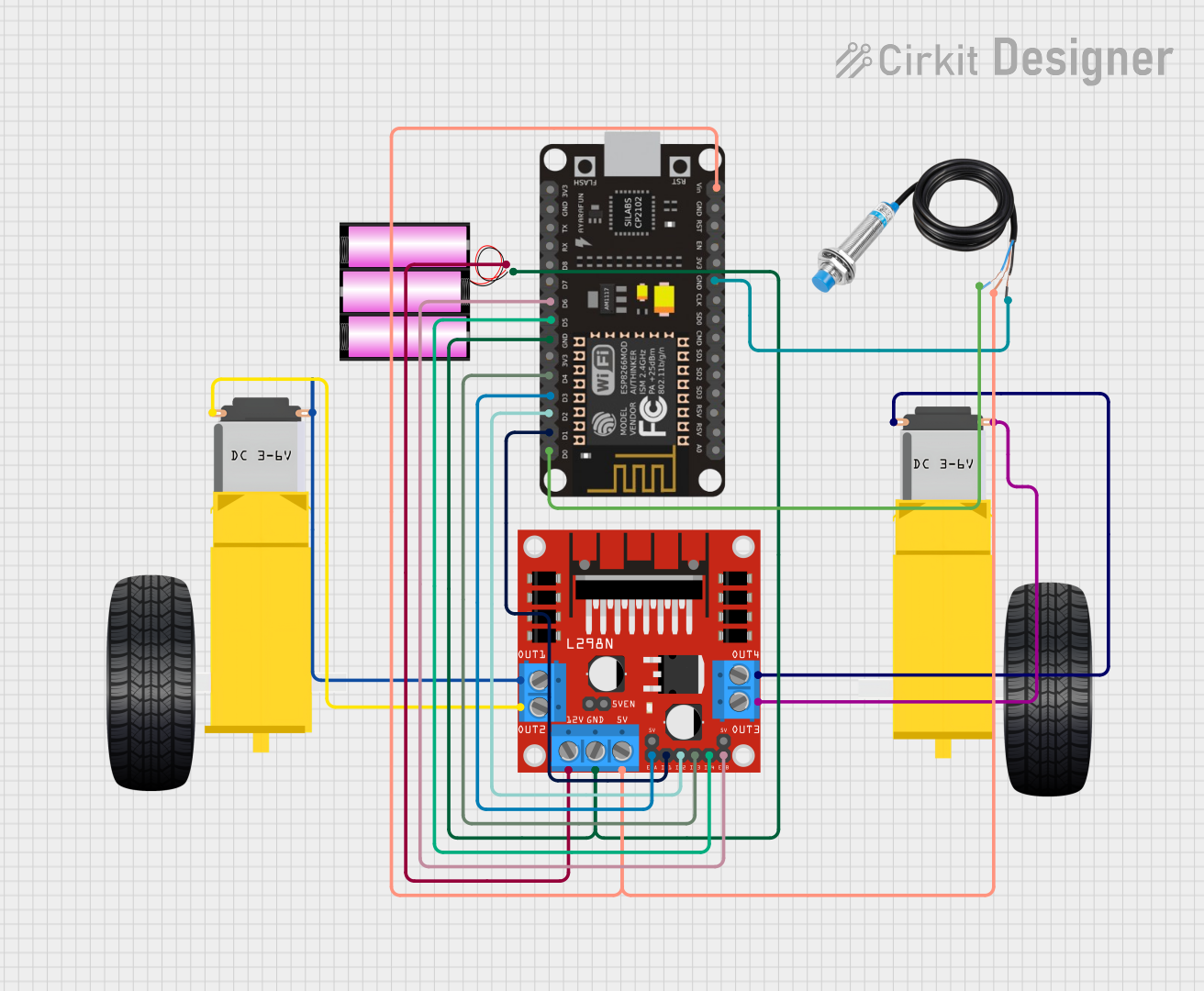
Circuit Documentation
Summary
This circuit is designed to control a vehicle with two DC gearmotors using an ESP8266 NodeMCU microcontroller. The microcontroller interfaces with an L298N DC motor driver to control the direction and speed of the motors. Additionally, the circuit includes a metal detection sensor that provides input to the microcontroller. The ESP8266 NodeMCU is also equipped with Wi-Fi capabilities, allowing for remote control via a web server.
Component List
ESP8266 NodeMCU
- Microcontroller with Wi-Fi capability.
- Pins: D0, D1, D2, D3, D4, 3V3, GND, D5, D6, D7, D8, RX, TX, A0, RSV, SD3, SD2, SD1, CMD, SD0, CLK, EN, RST, VIN.
L298N DC Motor Driver
- Dual H-bridge motor driver for controlling two DC motors.
- Pins: OUT1, OUT2, 12V, GND, 5V, OUT3, OUT4, 5V-ENA-JMP-I, 5V-ENA-JMP-O, +5V-J1, +5V-J2, ENA, IN1, IN2, IN3, IN4, ENB.
Gearmotor DC Wheels (Left and Right)
- DC gearmotors used for the vehicle's wheels.
- Pins: PIN1, PIN2.
Battery 12V
- Power source for the motor driver and the motors.
- Pins: +, -.
Metal Detection Sensor
- Sensor to detect the presence of metal.
- Pins: POWER, GND, OUT.
Wiring Details
ESP8266 NodeMCU
- D0 connected to Metal Detection Sensor OUT.
- D1 connected to L298N IN1.
- D2 connected to L298N IN2.
- D3 connected to L298N ENA.
- D4 connected to L298N IN3.
- D5 connected to L298N IN4.
- D6 connected to L298N ENB.
- GND connected to L298N GND and Metal Detection Sensor GND.
- VIN connected to L298N 5V and Metal Detection Sensor POWER.
L298N DC Motor Driver
- IN1, IN2, IN3, IN4 connected to ESP8266 NodeMCU D1, D2, D4, D5 respectively.
- ENA, ENB connected to ESP8266 NodeMCU D3, D6 respectively.
- OUT1, OUT2 connected to Left Gearmotor DC Wheels PIN1, PIN2.
- OUT3, OUT4 connected to Right Gearmotor DC Wheels PIN1, PIN2.
- 12V connected to Battery 12V +.
- GND connected to Battery 12V - and ESP8266 NodeMCU GND.
- 5V connected to ESP8266 NodeMCU VIN and Metal Detection Sensor POWER.
Gearmotor DC Wheels Left
- PIN1 connected to L298N OUT1.
- PIN2 connected to L298N OUT2.
Gearmotor DC Wheels Right
- PIN1 connected to L298N OUT3.
- PIN2 connected to L298N OUT4.
Battery 12V
-
- connected to L298N 12V.
-
- connected to L298N GND.
Metal Detection Sensor
- OUT connected to ESP8266 NodeMCU D0.
- GND connected to ESP8266 NodeMCU GND.
- POWER connected to ESP8266 NodeMCU VIN.
Documented Code
#include <ESP8266WiFi.h>
#include <ESP8266WebServer.h>

// Motor pins
#define IN1 D1
#define IN2 D2
#define ENA D3
#define IN3 D4
#define IN4 D5
#define ENB D6

// Metal sensor pin
#define METAL_SENSOR_PIN D7

// Wi-Fi credentials
const char* ssid = "Your_SSID";   // Replace with your WiFi SSID
const char* password = "Your_PASSWORD"; // Replace with your WiFi Password

ESP8266WebServer server(80); // Create a web server object on port 80

bool metalDetected = false; // Variable to store metal detection status

// Forward Function
void forward() {
  digitalWrite(IN1, HIGH);
  digitalWrite(IN2, LOW);
  digitalWrite(IN3, HIGH);
  digitalWrite(IN4, LOW);
}

// Backward Function
void backward() {
  digitalWrite(IN1, LOW);
  digitalWrite(IN2, HIGH);
  digitalWrite(IN3, LOW);
  digitalWrite(IN4, HIGH);
}

// Left Turn Function
void left() {
  digitalWrite(IN1, LOW);
  digitalWrite(IN2, HIGH);
  digitalWrite(IN3, HIGH);
  digitalWrite(IN4, LOW);
}

// Right Turn Function
void right() {
  digitalWrite(IN1, HIGH);
  digitalWrite(IN2, LOW);
  digitalWrite(IN3, LOW);
  digitalWrite(IN4, HIGH);
}

// Stop Function
void stopCar() {
  digitalWrite(IN1, LOW);
  digitalWrite(IN2, LOW);
  digitalWrite(IN3, LOW);
  digitalWrite(IN4, LOW);
}

// Handle root URL
void handleRoot() {
  String html = "<html><body><h1>WiFi Controlled Car</h1>";
  html += "<a href=\"/forward\">Forward</a><br>";
  html += "<a href=\"/backward\">Backward</a><br>";
  html += "<a href=\"/left\">Left</a><br>";
  html += "<a href=\"/right\">Right</a><br>";
  html += "<a href=\"/stop\">Stop</a><br>";

  if (metalDetected) {
    html += "<h2 style='color:red;'>Metal Detected!</h2>";
  } else {
    html += "<h2>No Metal Detected</h2>";
  }

  html += "</body></html>";
  server.send(200, "text/html", html);
}

// Handle forward request
void handleForward() {
  forward();
  server.send(200, "text/html", "Moving forward...<br><a href='/'>Go Back</a>");
}

// Handle backward request
void handleBackward() {
  backward();
  server.send(200, "text/html", "Moving backward...<br><a href='/'>Go Back</a>");
}

// Handle left request
void handleLeft() {
  left();
  server.send(200, "text/html", "Turning left...<br><a href='/'>Go Back</a>");
}

// Handle right request
void handleRight() {
  right();
  server.send(200, "text/html", "Turning right...<br><a href='/'>Go Back</a>");
}

// Handle stop request
void handleStop() {
  stopCar();
  server.send(200, "text/html", "Stopping...<br><a href='/'>Go Back</a>");
}

void setup() {
  // Set motor pins as output
  pinMode(IN1, OUTPUT);
  pinMode(IN2, OUTPUT);
  pinMode(ENA, OUTPUT);
  pinMode(IN3, OUTPUT);
  pinMode(IN4, OUTPUT);
  pinMode(ENB, OUTPUT);

  // Set metal sensor pin as input
  pinMode(METAL_SENSOR_PIN, INPUT);

  // Initialize serial communication
  Serial.begin(115200);

  // Start WiFi
  WiFi.begin(ssid, password);
  Serial.print("Connecting to WiFi...");
  while (WiFi.status() != WL_CONNECTED) {
    delay(1000);
    Serial.print(".");
  }
  Serial.println("Connected to WiFi");

  // Start web server routes
  server.on("/", handleRoot);
  server.on("/forward", handleForward);
  server.on("/backward", handleBackward);
  server.on("/left", handleLeft);
  server.on("/right", handleRight);
  server.on("/stop", handleStop);

  server.begin(); // Start the server
  Serial.println("Web server started.");
}

void loop() {
  server.handleClient(); // Handle client requests

  // Check metal sensor status
  metalDetected = digitalRead(METAL_SENSOR_PIN) == HIGH;
}
This code is designed to run on the ESP8266 NodeMCU microcontroller. It sets up a Wi-Fi connection and a web server to control the vehicle's movement and monitor the metal detection sensor. The vehicle can move forward, backward, turn left, turn right, or stop based on web requests. The metal detection status is also displayed on the web interface.