
Wireless Traffic Light Control System with Arduino Nano and NRF24L01 Modules
View and Edit Project In Cirkit Designer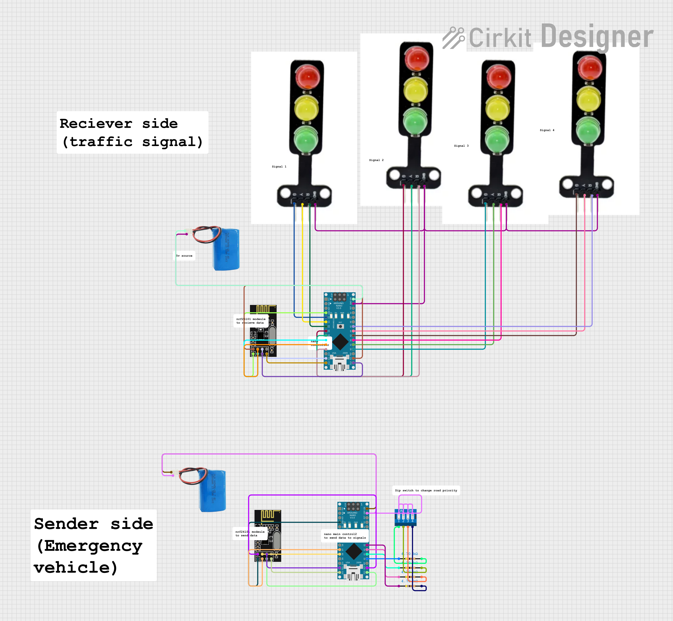
Circuit Documentation
Summary
The circuit in question appears to be a wireless control system utilizing two Arduino Nano microcontrollers and two NRF24L01 wireless transceiver modules. The system also includes multiple traffic light modules, each with red, yellow, and green LEDs, and a DIP switch for input configuration. Power is supplied by two 5V batteries. The circuit is designed to control the traffic lights wirelessly, with the potential for input configuration via the DIP switch. The Arduinos are programmed with placeholder code, which suggests that the specific control logic is yet to be implemented.
Component List
Microcontrollers
- Arduino Nano: A compact microcontroller board based on the ATmega328P, featuring digital and analog I/O pins.
Wireless Modules
- NRF24L01: A 2.4GHz wireless transceiver module, used for wireless data transmission.
Input Devices
- DIP Switch 4 Position: A manual electric switch packaged in a standard dual in-line package, used for setting the configuration of the circuit.
Output Devices
- Traffic Light Module: A module with three LEDs (red, yellow, green) representing a traffic light.
Power Supply
- 5V Battery: Provides the necessary power to the circuit components.
Passive Components
- Resistor (4700 Ohms): Used to limit current or divide voltages within the circuit.
Miscellaneous
- Comment: Placeholder for additional notes or comments within the circuit design.
Wiring Details
Arduino Nano
- Digital Pins (D2-D9, D11-D13): Connected to traffic light modules and NRF24L01 modules for control signals.
- Analog Pins (A0-A5): Connected to traffic light modules and resistors for additional control or sensing.
- Power Pins (VIN, 3V3, GND): Connected to the 5V batteries and NRF24L01 modules for power supply and common ground.
NRF24L01
- Data Pins (MOSI, MISO, SCK, CSN, CE): Interfaced with corresponding pins on the Arduino Nano for SPI communication.
- Power Pins (VCC, GND): Connected to the 3.3V output on the Arduino Nano and common ground.
Traffic Light Module
- LED Pins (Red, Yellow, Green): Controlled by digital or analog pins on the Arduino Nano.
- Ground (GND): Connected to the common ground.
DIP Switch 4 Position
- Switch Pins (1-8): Connected to the common ground and resistors for input configuration.
Resistor (4700 Ohms)
- Pins (pin1, pin2): Connected between the DIP switch and the Arduino Nano analog pins for voltage division.
Documented Code
Arduino Nano (Primary Controller)
void setup() {
  // put your setup code here, to run once:

}

void loop() {
  // put your main code here, to run repeatedly:

}
Filename: sketch.ino
Arduino Nano (Secondary Controller)
void setup() {
  // put your setup code here, to run once:

}

void loop() {
  // put your main code here, to run repeatedly:

}
Filename: sketch.ino
Note: The provided code is a template and does not contain any specific logic for controlling the traffic lights or wireless communication. The actual implementation needs to be developed based on the requirements of the circuit's application.