Cirkit Designer
Your all-in-one circuit design IDE
Home /
Project Documentation
Arduino Nano-Controlled Environment Monitoring and Stepper Motor System

Circuit Documentation
Summary
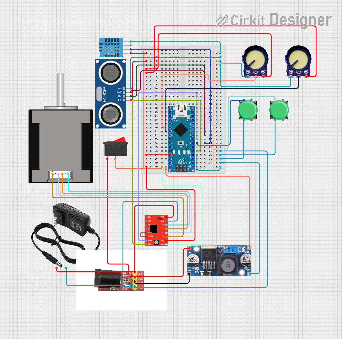
This circuit integrates various components controlled by an Arduino Nano microcontroller to perform a range of functions. It includes a stepper motor driver for motor control, a power supply system, sensors for environmental data, and user input devices. The circuit is designed to be powered by a 12V power supply, with a step-down buck converter to regulate voltage for the Arduino Nano and other components.
Component List
Microcontroller
- Arduino Nano: A compact microcontroller board based on the ATmega328P, featuring digital and analog I/O pins.
Motor Driver
- A4988 Stepper Motor Driver (Red): A complete microstepping motor driver with a built-in translator for easy operation.
Power Supply
- 12V Power Supply: Provides the main power source for the circuit.
- Power Supply Module: Assists in distributing power to various components.
- Step Down Buck Converter: Reduces the voltage from the power supply to a level suitable for the microcontroller and other components.
Sensors
- DHT11 Humidity and Temperature Sensor: Measures ambient temperature and humidity.
- HC-SR04 Ultrasonic Sensor: Measures distance by emitting ultrasonic waves and detecting their reflection.
Actuators
- Nema 17 42-STH48: A stepper motor commonly used for precision control in applications such as 3D printers and CNC machines.
User Input
- Potentiometer (x2): Variable resistors used to adjust voltage and provide analog input to the microcontroller.
- Pushbutton (x2): Momentary switches that provide a digital input to the microcontroller.
- Rocker Switch: A switch used to control the power supply to the circuit.
Wiring Details
Arduino Nano
- Analog Input A1 connected to Potentiometer Output.
- Analog Input A2 connected to Potentiometer Output.
- Digital Pin D7 connected to HC-SR04 Ultrasonic Sensor ECHO.
- Digital Pin D6 connected to HC-SR04 Ultrasonic Sensor TRIG.
- Digital Pin D5 connected to A4988 Stepper Motor Driver STEP.
- Digital Pin D4 connected to Pushbutton Pin 1 and DHT11 Humidity and Temperature Sensor DATA.
- Digital Pin D3 connected to Pushbutton Pin 1.
- Digital Pin D2 connected to A4988 Stepper Motor Driver DIR.
- 5V Output connected to DHT11 VDD, HC-SR04 VCC, Potentiometer VCC, and A4988 VDD.
- GND connected to DHT11 GND, HC-SR04 GND, Potentiometer GND, A4988 GND, 12V Power Supply -, Power Supply Module -, Pushbutton Pin 2, and Step Down Buck Converter OUT - GND.
- VIN connected to Rocker Switch Pin 2 and Step Down Buck Converter OUT +.
A4988 Stepper Motor Driver (Red)
- RESET connected to SLEEP.
- VMOT connected to 12V Power Supply + and Power Supply Module +.
- 2B connected to Nema 17 42-STH48 B1 Blue.
- 2A connected to Nema 17 42-STH48 B2 Red.
- 1A connected to Nema 17 42-STH48 A1 Green.
- 1B connected to Nema 17 42-STH48 A2 (black).
Power Supply Components
- Rocker Switch Pin 1 connected to Step Down Buck Converter IN + and Power Supply Module +.
- Step Down Buck Converter IN - GND connected to Power Supply Module -.
Documented Code
Arduino Nano Code (sketch.ino)
void setup() {
  // put your setup code here, to run once:

}

void loop() {
  // put your main code here, to run repeatedly:

}
Note: The provided code is a template and does not include specific functionality. It should be populated with the required setup and loop code to control the connected components based on the circuit design.