
ESP32-Based Smart Access Control System with RFID, Ultrasonic Sensor, and LCD Display
View and Edit Project In Cirkit Designer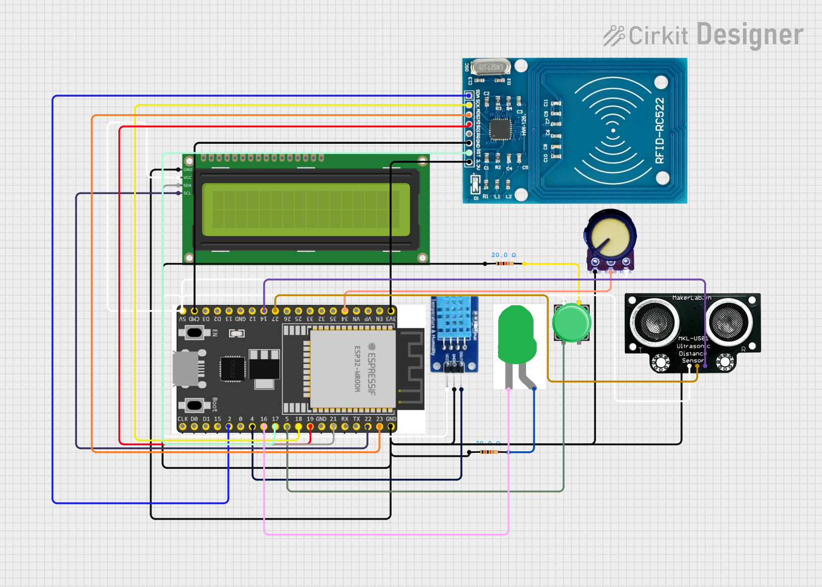
Circuit Documentation
Summary
This circuit is built around an ESP32 Wroom Dev Kit microcontroller and includes various sensors and peripherals such as an RFID reader, an ultrasonic distance sensor, a DHT11 temperature and humidity sensor, a potentiometer, an I2C LCD display, a pushbutton, and an LED. The circuit is designed to read RFID tags, measure distances, read temperature and humidity, and display information on an LCD. It also includes a potentiometer for analog input and a pushbutton for user interaction.
Component List
ESP32 Wroom Dev Kit
- Description: A powerful microcontroller with Wi-Fi and Bluetooth capabilities.
- Pins: 3V3, EN, VP, VN, GPIO 34, GPIO 35, GPIO 32, GPIO 33, GPIO 25, GPIO 26, GPIO 27, GPIO 14, GND, GPIO 13, SD2, SD3, CMD, V5, GPIO 23, GPIO 22, TXD, RXD, GPIO 21, GPIO 19, GPIO 18, GPIO 5, GPIO 17, GPIO 16, GPIO 4, GPIO 0, GPIO 2, GPIO 15, SD1, SD0, CLK
LED: Two Pin (green)
- Description: A simple green LED.
- Pins: Cathode, Anode
Resistor (20 Ohms)
- Description: A resistor with a resistance of 20 Ohms.
- Pins: Pin1, Pin2
Pushbutton
- Description: A four-pin pushbutton.
- Pins: Pin 1, Pin 2, Pin 3, Pin 4
Potentiometer
- Description: A variable resistor with three pins.
- Pins: GND, Output, VCC
DHT11
- Description: A temperature and humidity sensor.
- Pins: DATA, GND, VCC
16x2 I2C LCD
- Description: A 16x2 character LCD with I2C interface.
- Pins: GND, VCC, SDA, SCL
RFID-RC522
- Description: An RFID reader module.
- Pins: VCC (3.3V), RST, GND, IRQ, MISO, MOSI, SCK, SDA
MKE-S01 Ultrasonic Distance Sensor
- Description: An ultrasonic distance sensor.
- Pins: GND, 5V, TRIG, ECHO
Wiring Details
ESP32 Wroom Dev Kit
- 3V3 connected to RFID-RC522 VCC (3.3V)
- GPIO 34 connected to Potentiometer Output
- GPIO 27 connected to MKE-S01 Ultrasonic Distance Sensor TRIG
- GPIO 14 connected to MKE-S01 Ultrasonic Distance Sensor ECHO
- CMD connected to RFID-RC522 GND
- V5 connected to:
- 16x2 I2C LCD VCC
- Pushbutton Pin 1
- MKE-S01 Ultrasonic Distance Sensor 5V
- DHT11 VCC
- Potentiometer VCC
- GND connected to:
- 16x2 I2C LCD GND
- Resistor Pin1
- MKE-S01 Ultrasonic Distance Sensor GND
- DHT11 GND
- Resistor Pin1
- Potentiometer GND
- GPIO 23 connected to RFID-RC522 MOSI
- GPIO 22 connected to 16x2 I2C LCD SCL
- GPIO 21 connected to 16x2 I2C LCD SDA
- GPIO 19 connected to RFID-RC522 MISO
- GPIO 18 connected to RFID-RC522 SCK
- GPIO 5 connected to Pushbutton Pin 2
- GPIO 17 connected to RFID-RC522 RST
- GPIO 16 connected to LED Cathode
- GPIO 4 connected to DHT11 DATA
- GPIO 2 connected to RFID-RC522 SDA
LED: Two Pin (green)
- Cathode connected to ESP32 GPIO 16
- Anode connected to Resistor Pin2
Resistor (20 Ohms)
- Pin1 connected to ESP32 GND
- Pin2 connected to LED Anode
Pushbutton
- Pin 1 connected to ESP32 V5
- Pin 2 connected to ESP32 GPIO 5
- Pin 3 connected to Resistor Pin2
- Pin 4 not connected
Potentiometer
- GND connected to ESP32 GND
- Output connected to ESP32 GPIO 34
- VCC connected to ESP32 V5
DHT11
- DATA connected to ESP32 GPIO 4
- GND connected to ESP32 GND
- VCC connected to ESP32 V5
16x2 I2C LCD
- GND connected to ESP32 GND
- VCC connected to ESP32 V5
- SDA connected to ESP32 GPIO 21
- SCL connected to ESP32 GPIO 22
RFID-RC522
- VCC (3.3V) connected to ESP32 3V3
- RST connected to ESP32 GPIO 17
- GND connected to ESP32 CMD
- MISO connected to ESP32 GPIO 19
- MOSI connected to ESP32 GPIO 23
- SCK connected to ESP32 GPIO 18
- SDA connected to ESP32 GPIO 2
MKE-S01 Ultrasonic Distance Sensor
- GND connected to ESP32 GND
- 5V connected to ESP32 V5
- TRIG connected to ESP32 GPIO 27
- ECHO connected to ESP32 GPIO 14
Code Documentation
#include <Wire.h>
#include <LCD_I2C.h>  //LCD_I2C 2.3.0 by Blackhack
#include <MFRC522.h>  //MFRC522-spi-i2c-uart-async by MiguelBalboa 1.5.1
#include <DFRobot_DHT11.h>

#define DHT11_PIN 4
#define RST_PIN 17
#define SS_PIN 2
#define LED_PIN 16
#define BUTTON_PIN 5
#define POT_PIN 34

// RFID variables
byte readCard[4];
String MasterTag = "ENTER_YOUR_TAG_ID";
String tagID = "";

// Create instances
MFRC522 mfrc522(SS_PIN, RST_PIN);
LCD_I2C lcd(0x3F, 16, 2);  // Default address of most PCF8574 modules, change according
DFRobot_DHT11 dht(DHT11_PIN);

// Button variables
const int botao = 2;
unsigned long tempoInicio = 0;
unsigned long tempoFim = 0;
unsigned long tempoAbastecendo = 0;
bool botaoPressionado = false;

// Potentiometer and sensor variables
const int potPin = 34;
const int sensorRetirada = 2;
const int sensorRetorno = 3;
bool acessoLiberado = false;
bool bombaRemovida = false;

// Ultrasonic sensor pins
const int trigPin = 27;
const int echoPin = 14;

unsigned long lastMillis = 0;
const int incrementValue = 15;
int incrementedValue = 0;

long duration;
float distance;
float litros;

void setup() {
  Serial.begin(9600);
  pinMode(trigPin, OUTPUT);
  pinMode(echoPin, INPUT);
  lcd.begin();
  lcd.backlight();
  SPI.begin();
  mfrc522.PCD_Init();
  delay(4);
  lcd.setCursor(0, 0);
  lcd.print("Controle de Acesso");
  lcd.setCursor(0, 1);
  lcd.print("Passe seu cartao");
}

void loop() {
  unsigned long currentMillis = millis();
  int potValue = analogRead(potPin);

  if (acessoLiberado) {
    lcd.clear();
    lcd.setCursor(0, 0);
    lcd.print(String(potValue));
    lcd.setCursor(0, 1);
    lcd.print("Aba:");
    lcd.print(incrementedValue);

    if (currentMillis - lastMillis >= 1) {
      lastMillis = currentMillis;
      Serial.println("incrementedValue:" + String(incrementedValue));
      if (incrementedValue < potValue) {
        Serial.println("Menor");
        incremented