Cirkit Designer
Your all-in-one circuit design IDE
Home /
Project Documentation
Arduino UNO Controlled Sequential LED Lighting Pattern

Circuit Documentation
Summary
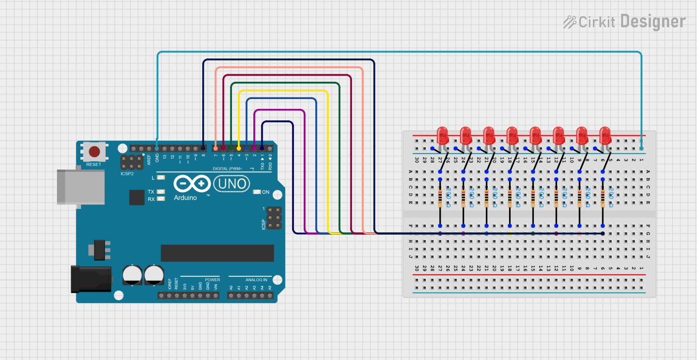
This circuit is designed to control a sequence of eight red LEDs using an Arduino UNO microcontroller. Each LED is connected to a digital output pin on the Arduino through a 200 Ohm resistor. The LEDs light up in a sequence, creating a simple lighting pattern as dictated by the embedded code running on the Arduino UNO.
Component List
Microcontroller
- Arduino UNO: A microcontroller board based on the ATmega328P. It has 14 digital input/output pins, 6 analog inputs, a USB connection, a power jack, an ICSP header, and a reset button.
LEDs
- LED: Two Pin (red): A basic red light-emitting diode with two pins: an anode and a cathode.
Resistors
- Resistor: A passive two-terminal electrical component that implements electrical resistance as a circuit element. In this circuit, resistors are used to limit the current flowing through the LEDs. Each resistor has a value of 200 Ohms.
Wiring Details
Arduino UNO
- Digital Pins D1-D8: Connected to one side of the resistors.
- GND: Connected to the cathodes of all LEDs.
LEDs
- Anode: Connected to one side of the corresponding resistor.
- Cathode: Connected to the GND pin on the Arduino UNO.
Resistors
- Pin1: Connected to the anode of the corresponding LED.
- Pin2: Connected to a digital pin (D1-D8) on the Arduino UNO.
Documented Code
Arduino UNO Code
/*
 * This Arduino Sketch controls 8 LEDs connected to an Arduino UNO.
 * The LEDs will light up in a sequence, creating a simple lighting pattern.
 */

int led1 = 1;
int led2 = 2;
int led3 = 3;
int led4 = 4;
int led5 = 5;
int led6 = 6;
int led7 = 7;
int led8 = 8;

void setup() {
  pinMode(led1, OUTPUT);
  pinMode(led2, OUTPUT);
  pinMode(led3, OUTPUT);
  pinMode(led4, OUTPUT);
  pinMode(led5, OUTPUT);
  pinMode(led6, OUTPUT);
  pinMode(led7, OUTPUT);
  pinMode(led8, OUTPUT);
}

void loop() {
  int t = 100; // delay time in milliseconds
  digitalWrite(led1, HIGH);
  delay(t);
  digitalWrite(led1, LOW);
  digitalWrite(led2, HIGH);
  delay(t);
  digitalWrite(led2, LOW);
  digitalWrite(led3, HIGH);
  delay(t);
  digitalWrite(led3, LOW);
  digitalWrite(led4, HIGH);
  delay(t);
  digitalWrite(led4, LOW);
  digitalWrite(led5, HIGH);
  delay(t);
  digitalWrite(led5, LOW);
  digitalWrite(led6, HIGH);
  delay(t);
  digitalWrite(led6, LOW);
  digitalWrite(led7, HIGH);
  delay(t);
  digitalWrite(led7, LOW);
  digitalWrite(led8, HIGH);
  delay(t);
  digitalWrite(led8, LOW);
}
This code is designed to sequentially turn on and off each LED connected to the digital pins D1 to D8 of the Arduino UNO. The setup() function initializes these pins as outputs. The loop() function then turns each LED on and off in sequence with a delay of 100 milliseconds between each action.