Cirkit Designer
Your all-in-one circuit design IDE
Home /
Project Documentation
ESP32-CAM and Arduino Nano Touch-Activated Security System with Buzzer and LED
Circuit Documentation
Summary
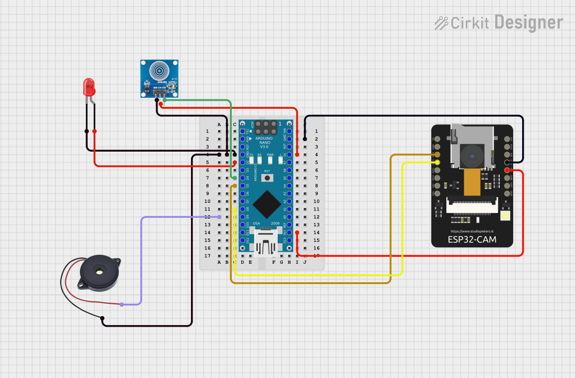
This circuit involves an Arduino Nano microcontroller interfacing with a touch sensor, a red LED, a buzzer, and an ESP32-CAM module. The touch sensor is used to detect user input, which then controls the LED and buzzer. The ESP32-CAM module is also integrated into the circuit for additional functionality.
Component List
Touch Sensor
- Pins: IO, VCC, GND
- Description: A touch sensor used to detect user input.
- Purpose in Circuit: Detects touch input to control other components.
LED: Two Pin (red)
- Pins: Cathode, Anode
- Description: A red LED.
- Purpose in Circuit: Provides visual feedback when the touch sensor is activated.
ESP32 - CAM
- Pins: 5V, GND, IO12, IO13, IO15, IO14, IO2, IO4, VOT, VOR, VCC, IO0, IO16, 3V3
- Description: A camera module with Wi-Fi capabilities.
- Purpose in Circuit: Provides additional functionality, potentially for capturing images or video.
Buzzer
- Pins: GND, IN
- Description: A buzzer.
- Purpose in Circuit: Provides audio feedback when the touch sensor is activated.
Arduino Nano
- Pins: D1/TX, D0/RX, RESET, GND, D2, D3, D4, D5, D6, D7, D8, D9, D10, D11/MOSI, D12/MISO, VIN, 5V, A7, A6, A5, A4, A3, A2, A1, A0, AREF, 3V3, D13/SCK
- Description: A small, complete, and breadboard-friendly microcontroller board.
- Purpose in Circuit: Acts as the main controller for the circuit.
Wiring Details
Touch Sensor
- IO connected to D4 of Arduino Nano
- VCC connected to 5V of Arduino Nano
- GND connected to GND of Arduino Nano
LED: Two Pin (red)
- Anode connected to D2 of Arduino Nano
- Cathode connected to GND of Arduino Nano
ESP32 - CAM
- IO12 connected to D5 of Arduino Nano
- IO13 connected to D8 of Arduino Nano
- VCC connected to 3V3 of Arduino Nano
- GND connected to GND of Arduino Nano
Buzzer
- IN connected to D9 of Arduino Nano
- GND connected to GND of Arduino Nano
Arduino Nano
- D4 connected to IO of Touch Sensor
- 5V connected to VCC of Touch Sensor
- GND connected to GND of Touch Sensor, LED, and Buzzer
- D2 connected to Anode of LED
- D5 connected to IO12 of ESP32 - CAM
- D8 connected to IO13 of ESP32 - CAM
- 3V3 connected to VCC of ESP32 - CAM
- GND connected to GND of ESP32 - CAM
- D9 connected to IN of Buzzer
Code Documentation
Arduino Nano Code
#define BUTTON_PIN 4
#define USER_PIN 8

int isPressed = LOW, pres_state = LOW;

void setup()
{
  pinMode(BUTTON_PIN, INPUT);
  pinMode(USER_PIN, INPUT);

  pinMode(2, OUTPUT);
  pinMode(9, OUTPUT);
  pinMode(5, OUTPUT);
}

void loop()
{
    if(digitalRead(USER_PIN) == HIGH && pres_state == LOW) pres_state = HIGH;
    else if(digitalRead(USER_PIN) == HIGH && pres_state == HIGH) pres_state = LOW;

    isPressed = digitalRead(BUTTON_PIN);

    if (isPressed != LOW && pres_state == HIGH)
    {
        digitalWrite(9, HIGH);
        digitalWrite(2, HIGH);
        digitalWrite(5, HIGH);
    }
    else
    {
        digitalWrite(9, LOW);
        digitalWrite(2, LOW);
        digitalWrite(5, LOW);
    }
}
Code Explanation
- BUTTON_PIN and USER_PIN are defined as pins 4 and 8 respectively.
- The
setup()function initializes the pin modes for the touch sensor, LED, and buzzer. - The
loop()function continuously checks the state of the touch sensor and user input. - If the touch sensor is pressed and the user input is active, the LED and buzzer are turned on.
- If the touch sensor is not pressed or the user input is inactive, the LED and buzzer are turned off.