Cirkit Designer
Your all-in-one circuit design IDE
Home /
Project Documentation
Arduino-Controlled Robotics Platform with Servo Drivers and DC Motor Management
Circuit Documentation
Summary
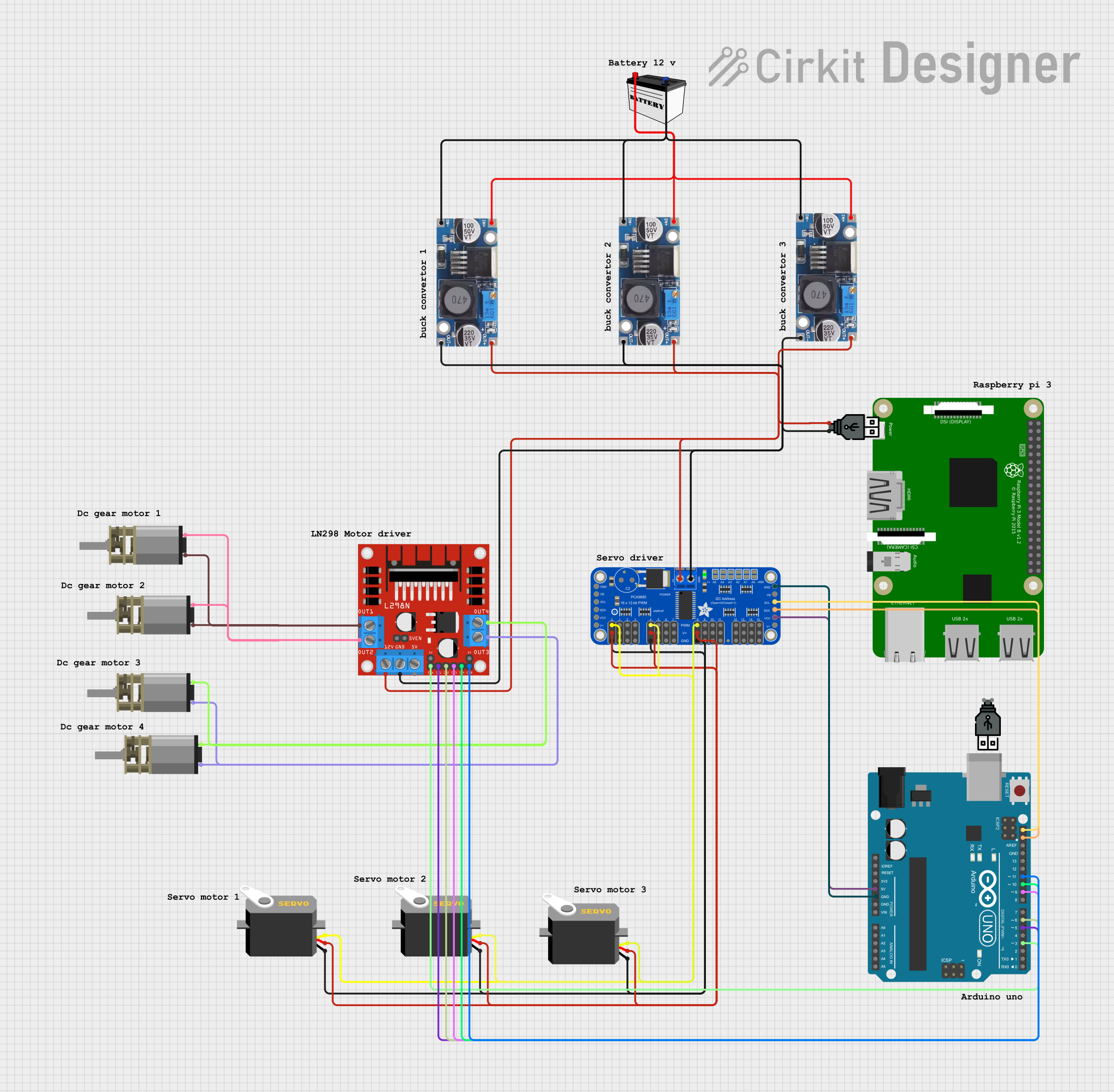
This circuit is designed to utilize a 12V battery as a power source, which is then stepped down to appropriate voltages for various components using step-down buck converters. The circuit includes a microcontroller (Arduino UNO), a Raspberry Pi 3B, a PWM servo driver for controlling multiple servos, a DC motor driver for controlling DC motors, and several DC mini metal gear motors and servos. The microcontroller is programmed to interface with the motor driver and the PWM servo driver, which in turn control the motors and servos, respectively.
Component List
Power Supply
- 12V Battery (Small Size): Provides the main power source for the circuit.
Voltage Regulation
- Step down Buck converters: Three instances are used to step down the voltage from the 12V battery to lower voltages required by other components.
Microcontrollers
- Arduino UNO: Acts as the main controller for the circuit, interfacing with the motor driver and the PWM servo driver.
- Raspberry Pi 3B: A powerful microcomputer that can be used for more complex processing tasks.
Motor Control
- L298N DC motor driver: Controls the direction and speed of DC motors.
- DC Mini Metal Gear Motors: Four instances of motors that are driven by the L298N motor driver.
Servo Control
- Adafruit 16-Channel 12-bit PWM Servo Driver - I2C: Controls up to 16 servos via PWM signals.
- Servos: Three instances of servos controlled by the PWM servo driver.
Power Distribution
- USB power: Two instances are used to distribute power to components that require USB power input.
Wiring Details
12V Battery (Small Size)
- VCC connected to the input of all three Step down Buck converters.
- GND connected to the ground input of all three Step down Buck converters.
Step down Buck converters
- IN + connected to the VCC of the 12V Battery.
- IN - GND connected to the GND of the 12V Battery.
- OUT + and OUT - GND provide regulated voltage outputs to the following components:
- One converter powers the Adafruit PWM Servo Driver (PWRIN and GND).
- Another converter powers the USB power module.
- The third converter powers the L298N DC motor driver (12V and GND).
Adafruit 16-Channel 12-bit PWM Servo Driver - I2C
- PWRIN connected to the output of one Step down Buck converter.
- GND connected to the ground of the same Step down Buck converter.
- VCC, SDA, SCL, and GND connected to the corresponding pins on the Arduino UNO for I2C communication and power.
- PWM channels (PWM0, PWM4, PWM8) connected to the pulse pins of the Servos.
- 5.0V and GND pins connected to the vcc and gnd pins of the Servos, respectively.
Raspberry Pi 3B
- No specific wiring details provided.
Arduino UNO
- 5V and GND connected to the VCC and GND of the Adafruit PWM Servo Driver.
- SDA and SCL connected to the corresponding pins on the Adafruit PWM Servo Driver for I2C communication.
- Digital pins (D3, D5, D6, D9, D10, D11) connected to the control pins (ENA, IN1, IN2, IN3, IN4, ENB) of the L298N DC motor driver.
L298N DC motor driver
- 12V and GND connected to the output of one Step down Buck converter.
- Control pins (ENA, IN1, IN2, IN3, IN4, ENB) connected to the corresponding digital pins on the Arduino UNO.
- Output pins (OUT1, OUT2, OUT3, OUT4) connected to the input pins of the DC Mini Metal Gear Motors.
DC Mini Metal Gear Motors
- IN1 and IN2 of each motor connected to the corresponding output pins on the L298N DC motor driver.
Servos
- gnd and vcc connected to the GND and 5.0V pins of the Adafruit PWM Servo Driver.
- pulse connected to the corresponding PWM channels on the Adafruit PWM Servo Driver.
USB power
- No specific wiring details provided.
Documented Code
Arduino UNO Code (sketch.ino)
void setup() {
  // put your setup code here, to run once:

}

void loop() {
  // put your main code here, to run repeatedly:

}
Arduino UNO Documentation (documentation.txt)
No additional documentation provided for the code.