Wi-Fi Controlled ESP32-Based Smart Lock with RFID and OLED Display
Circuit Documentation
Summary of the Circuit
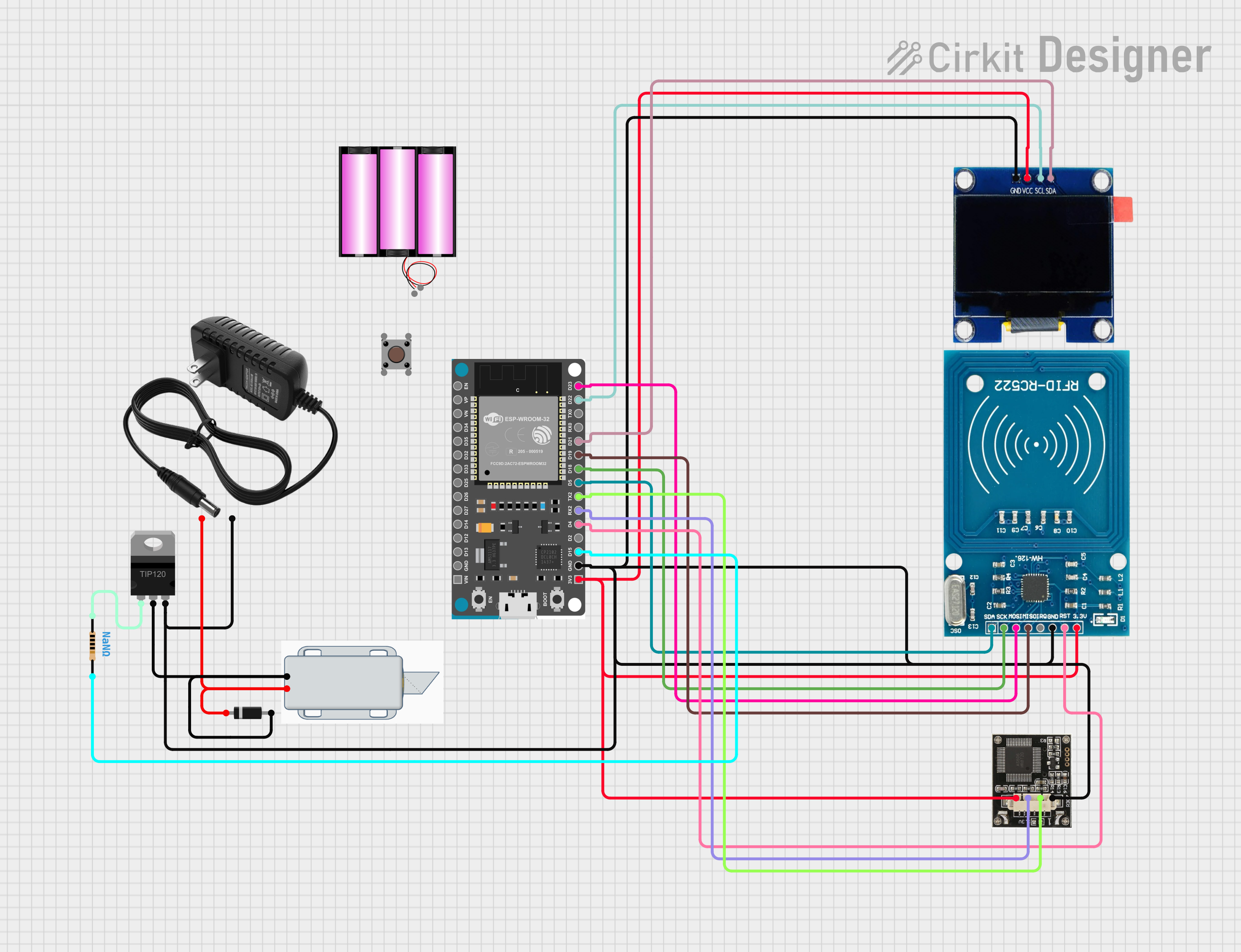
The circuit in question appears to be a smart lock system that can be controlled via Wi-Fi. It uses an ESP32 Devkit V1 microcontroller to manage the communication and control logic. The system includes an OLED display for user interface, an RFID-RC522 module for access control, and a r307 fingerprint sensor for biometric verification. A TIP120 Darlington Transistor is used to drive a 12V Solenoid Lock, which acts as the physical locking mechanism. The circuit is powered by a 12V power supply, and a diode is used to protect against reverse polarity. A pushbutton is also included, possibly for manual control.
Component List
Battery 12V
A power source for the circuit.
OLED 1.3"
A small display for outputting information to the user.
TIP120 Hi-Current Darlington Transistor
Used to switch high current loads with a low current control signal from the ESP32.
Resistor
A passive two-terminal electrical component that implements electrical resistance as a circuit element.
ESP32 Devkit V1
A microcontroller with Wi-Fi capabilities for controlling the circuit and communicating with external devices.
r307
A fingerprint sensor module for biometric input.
12V Power Supply
Provides a stable 12V power source for the circuit.
12V Solenoid Lock
An electromechanical lock controlled by the circuit.
RFID-RC522
An RFID reader/writer module for contactless communication using radio frequency.
Diode
A component that allows current to flow in one direction, used for reverse polarity protection.
Pushbutton
A simple switch mechanism for control of a circuit.
Wiring Details
Battery 12V
+to 12V power supply+-to 12V power supply-
OLED 1.3"
GNDto ESP32GNDVCCto ESP323V3SCLto ESP32D22SDAto ESP32D21
TIP120 Hi-Current Darlington Transistor
BASEto Resistorpin1COLLECTORto Diodeanodeand 12V Solenoid Lock-EMITTERto 12V power supply-
Resistor
pin1to TIP120BASEpin2to ESP32D15
ESP32 Devkit V1
3V3to OLEDVCC, r307VCC, and RFID-RC522VCC (3.3V)GNDto 12V power supply-, TIP120EMITTER, r307GND, RFID-RC522GND, and OLEDGNDD15to Resistorpin2D4to RFID-RC522RSTRX2to r307RXTX2to r307TXD5to RFID-RC522SDAD18to RFID-RC522SCKD19to RFID-RC522MISOD21to OLEDSDAD22to OLEDSCLD23to RFID-RC522MOSI
r307
VCCto ESP323V3RXto ESP32RX2TXto ESP32TX2GNDto ESP32GND
12V Power Supply
+to Diodecathodeand 12V Solenoid Lock+-to ESP32GNDand TIP120EMITTER
12V Solenoid Lock
+to Diodecathodeand 12V power supply+-to TIP120COLLECTOR
RFID-RC522
VCC (3.3V)to ESP323V3RSTto ESP32D4GNDto ESP32GNDIRQ(Not connected)MISOto ESP32D19MOSIto ESP32D23SCKto ESP32D18SDAto ESP32D5
Diode
anodeto TIP120COLLECTORand 12V Solenoid Lock-cathodeto 12V power supply+and 12V Solenoid Lock+
Pushbutton
Pin 3 (out)(Not connected)Pin 4 (out)(Not connected)Pin 1 (in)(Not connected)Pin 2 (in)(Not connected)
Documented Code
#include <WiFi.h>
#include <WebServer.h>

const char* ssid = "your_SSID";
const char* password = "your_PASSWORD";

WebServer server(80);

// Define GPIO pin for the relay
const int relayPin = 15;

void setup() {
  Serial.begin(115200);
  pinMode(relayPin, OUTPUT);
  digitalWrite(relayPin, HIGH);  // Lock is initially locked

  // Connect to Wi-Fi
  WiFi.begin(ssid, password);
  while (WiFi.status() != WL_CONNECTED) {
    delay(1000);
    Serial.println("Connecting to WiFi...");
  }

  Serial.println("Connected to WiFi");

  // Setup server routes
  server.on("/unlock", handleUnlock);
  server.begin();
  Serial.println("HTTP server started");
}

void handleUnlock() {
  digitalWrite(relayPin, LOW);  // Unlock the door
  delay(5000);  // Keep it unlocked for 5 seconds
  digitalWrite(relayPin, HIGH); // Lock again
  server.send(200, "text/plain", "Door unlocked");
}

void loop() {
  server.handleClient();
}
This code is designed to run on the ESP32 Devkit V1 microcontroller. It sets up a Wi-Fi connection and a web server that listens for an /unlock route. When this route is accessed, the ESP32 activates the relay connected to relayPin (GPIO 15), unlocking the door for 5 seconds before locking it again.