
Transistor-Based LED Control Circuit with Capacitors and Resistors
View and Edit Project In Cirkit Designer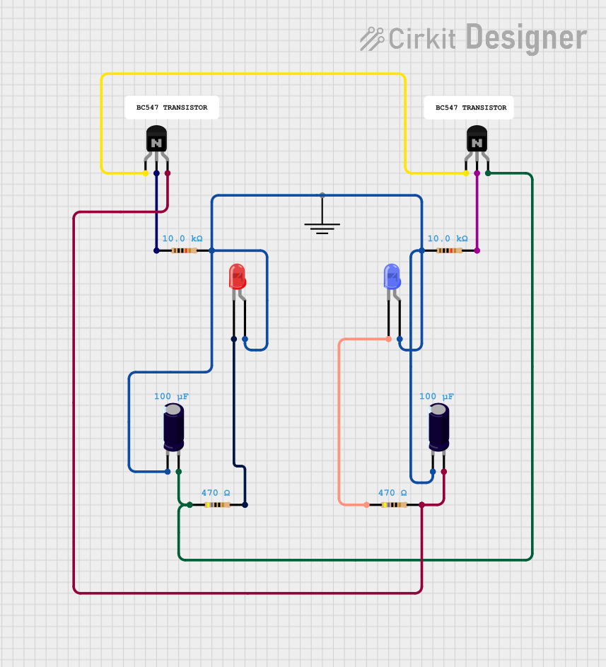
Circuit Documentation
Summary
This document provides a detailed overview of a circuit consisting of NPN transistors, resistors, electrolytic capacitors, and LEDs. The circuit is designed to demonstrate the interaction between these components, including the use of transistors as switches, resistors for current limiting, capacitors for filtering, and LEDs for visual indication.
Component List
NPN Transistor (EBC)
- Pins: emitter, base, collector
- Description: A standard NPN transistor used for switching and amplification.
Resistor
- Pins: pin1, pin2
- Description: A passive component used to limit current.
- Properties:
- Resistance: 10,000 Ohms
Resistor
- Pins: pin1, pin2
- Description: A passive component used to limit current.
- Properties:
- Resistance: 470 Ohms
Electrolytic Capacitor
- Pins: -, +
- Description: A polarized capacitor used for filtering and energy storage.
- Properties:
- Capacitance: 0.0001 Farads
LED: Two Pin (red)
- Pins: cathode, anode
- Description: A red light-emitting diode used for visual indication.
LED: Two Pin (blue)
- Pins: cathode, anode
- Description: A blue light-emitting diode used for visual indication.
GND
- Pins: GND
- Description: Ground connection for the circuit.
Wiring Details
NPN Transistor (EBC)
Transistor 1
- Emitter: Connected to the emitter of Transistor 2.
- Base: Connected to pin1 of a 10,000 Ohm resistor.
- Collector: Connected to pin2 of a 470 Ohm resistor and the positive pin of an electrolytic capacitor.
Transistor 2
- Emitter: Connected to the emitter of Transistor 1.
- Base: Connected to pin2 of a 10,000 Ohm resistor.
- Collector: Connected to pin1 of a 470 Ohm resistor and the positive pin of another electrolytic capacitor.
Resistor
10,000 Ohm Resistor 1
- Pin1: Connected to the base of Transistor 1.
- Pin2: Connected to the anode of the red LED, the anode of the blue LED, the negative pin of an electrolytic capacitor, pin1 of another 10,000 Ohm resistor, and the negative pin of another electrolytic capacitor.
10,000 Ohm Resistor 2
- Pin1: Connected to the base of Transistor 2.
- Pin2: Connected to the anode of the red LED, the anode of the blue LED, the negative pin of an electrolytic capacitor, pin1 of another 10,000 Ohm resistor, and the negative pin of another electrolytic capacitor.
470 Ohm Resistor 1
- Pin1: Connected to the collector of Transistor 2 and the positive pin of an electrolytic capacitor.
- Pin2: Connected to the cathode of the red LED.
470 Ohm Resistor 2
- Pin1: Connected to the collector of Transistor 1 and the positive pin of an electrolytic capacitor.
- Pin2: Connected to the cathode of the blue LED.
Electrolytic Capacitor
Capacitor 1
- Positive: Connected to pin1 of a 470 Ohm resistor and the collector of Transistor 2.
- Negative: Connected to pin2 of a 10,000 Ohm resistor, the anode of the red LED, the anode of the blue LED, pin1 of another 10,000 Ohm resistor, and the negative pin of another electrolytic capacitor.
Capacitor 2
- Positive: Connected to pin1 of a 470 Ohm resistor and the collector of Transistor 1.
- Negative: Connected to pin2 of a 10,000 Ohm resistor, the anode of the red LED, the anode of the blue LED, pin1 of another 10,000 Ohm resistor, and the negative pin of another electrolytic capacitor.
LED: Two Pin (red)
- Red LED
- Anode: Connected to pin2 of a 10,000 Ohm resistor, the anode of the blue LED, the negative pin of an electrolytic capacitor, pin1 of another 10,000 Ohm resistor, and the negative pin of another electrolytic capacitor.
- Cathode: Connected to pin2 of a 470 Ohm resistor.
LED: Two Pin (blue)
- Blue LED
- Anode: Connected to pin2 of a 10,000 Ohm resistor, the anode of the red LED, the negative pin of an electrolytic capacitor, pin1 of another 10,000 Ohm resistor, and the negative pin of another electrolytic capacitor.
- Cathode: Connected to pin1 of a 470 Ohm resistor.
GND
- Ground
- GND: Not explicitly connected in the provided net list.
Code
No microcontroller code is provided for this circuit.
This documentation provides a comprehensive overview of the circuit, including a summary, component list, wiring details, and code section. Each component is described, and its connections are detailed to ensure clarity and understanding.