
Arduino UNO and ESP8266 Nodemcu Controlled Servo and IR Sensor Array with Indicator LEDs
View and Edit Project In Cirkit Designer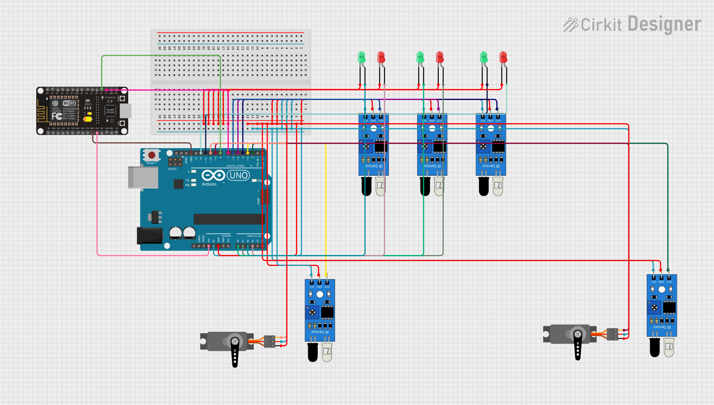
Circuit Documentation
Summary of the Circuit
The circuit in question appears to be a microcontroller-based system designed to interface with multiple infrared (IR) sensors, servo motors, and LEDs. The primary controller is an Arduino UNO, which is responsible for processing signals from the IR sensors and controlling the servos and LEDs accordingly. Additionally, an ESP8266 NodeMCU module is included, likely for adding Wi-Fi connectivity to the system. The IR sensors are used for input, the servos for actuation, and the LEDs as indicators.
Component List
Microcontrollers
- Arduino UNO: A microcontroller board based on the ATmega328P, featuring digital and analog I/O pins.
- ESP8266 NodeMCU: A Wi-Fi-enabled microcontroller module based on the ESP8266 chip, with digital pins and one analog input.
Sensors
- IR Sensors: Used to detect objects or movement. Each sensor has an output, ground, and power connection.
Actuators
- Servos: Electromechanical devices that can be precisely controlled for position. Each servo has a control (PWM), power, and ground connection.
Indicators
- LEDs (Red and Green): Light Emitting Diodes used as visual indicators. Each LED has an anode and cathode for power and ground connections, respectively.
Wiring Details
Arduino UNO
- Ground (GND): Connected to the ground pins of all IR sensors, servos, and the cathodes of all LEDs.
- 5V: Powers all IR sensors and servos.
- 3.3V: Connected to the 3V3 pin of the ESP8266 NodeMCU.
- Digital Pins (D2-D12): Connected to the output of IR sensors and the control (PWM) pins of servos, as well as the anodes of LEDs.
ESP8266 NodeMCU
- 3V3: Connected to the 3.3V pin of the Arduino UNO.
- Ground (GND): Shared with the Arduino UNO ground.
- RX: Connected to the D8 pin of the Arduino UNO.
- TX: Connected to the D7 pin of the Arduino UNO.
IR Sensors
- Output: Each sensor's output is connected to a unique digital pin on the Arduino UNO (D2-D6).
- Ground (GND): Common ground with Arduino UNO.
- VCC: Powered by the 5V pin from the Arduino UNO.
Servos
- PWM: Each servo's control pin is connected to a unique digital pin on the Arduino UNO (D9 and D10).
- VCC: Powered by the 5V pin from the Arduino UNO.
- Ground (GND): Common ground with Arduino UNO.
LEDs
- Anode: Connected to various digital pins on the Arduino UNO (A0-A3, D11, and D12) for red and green LEDs.
- Cathode: Common ground with Arduino UNO.
Documented Code
Arduino UNO Code (sketch.ino)
void setup() {
  // put your setup code here, to run once:

}

void loop() {
  // put your main code here, to run repeatedly:

}
Additional Notes
The provided code for the Arduino UNO is a template with empty setup() and loop() functions. Actual implementation details need to be added to control the IR sensors, servos, and LEDs based on the requirements of the application.
The ESP8266 NodeMCU code is not provided in the input and would be necessary to implement any Wi-Fi-related functionality.