Cirkit Designer
Your all-in-one circuit design IDE
Home /
Project Documentation
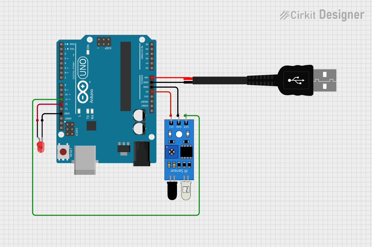
Arduino UNO-Based IR Sensor and LED Indicator with USB Power
Circuit Documentation
Summary
This circuit involves an Arduino UNO microcontroller, an IR sensor, a red LED, and a USB male 2-pin connection. The Arduino UNO is used to control the LED based on the input from the IR sensor. The USB connection provides power to the Arduino UNO.
Component List
Arduino UNO
- Description: A microcontroller board based on the ATmega328P.
- Pins: UNUSED, IOREF, Reset, 3.3V, 5V, GND, Vin, A0, A1, A2, A3, A4, A5, SCL, SDA, AREF, D13, D12, D11, D10, D9, D8, D7, D6, D5, D4, D3, D2, D1, D0
LED: Two Pin (red)
- Description: A red LED with two pins: cathode and anode.
- Pins: cathode, anode
IR Sensor
- Description: An infrared sensor with three pins: out, gnd, and vcc.
- Pins: out, gnd, vcc
USB Male 2 Pin Connection
- Description: A USB male connector with two pins: Negative (-) and Positive (+).
- Pins: Negative -, Positive +
Wiring Details
Arduino UNO
- 5V is connected to vcc of the IR sensor.
- GND is connected to gnd of the IR sensor.
- GND is connected to Negative (-) of the USB male 2-pin connection.
- Vin is connected to Positive (+) of the USB male 2-pin connection.
- GND is connected to cathode of the red LED.
- D12 is connected to anode of the red LED.
- D11 is connected to out of the IR sensor.
LED: Two Pin (red)
- cathode is connected to GND of the Arduino UNO.
- anode is connected to D12 of the Arduino UNO.
IR Sensor
- vcc is connected to 5V of the Arduino UNO.
- gnd is connected to GND of the Arduino UNO.
- out is connected to D11 of the Arduino UNO.
USB Male 2 Pin Connection
- Negative (-) is connected to GND of the Arduino UNO.
- Positive (+) is connected to Vin of the Arduino UNO.
Code Documentation
Arduino UNO Code
sketch.ino
void setup() {
  // put your setup code here, to run once:

}

void loop() {
  // put your main code here, to run repeatedly:

}
documentation.txt