
ESP32-WROOM-32UE Wi-Fi Controlled Robotic Car with OLED Display and RGB LED
View and Edit Project In Cirkit Designer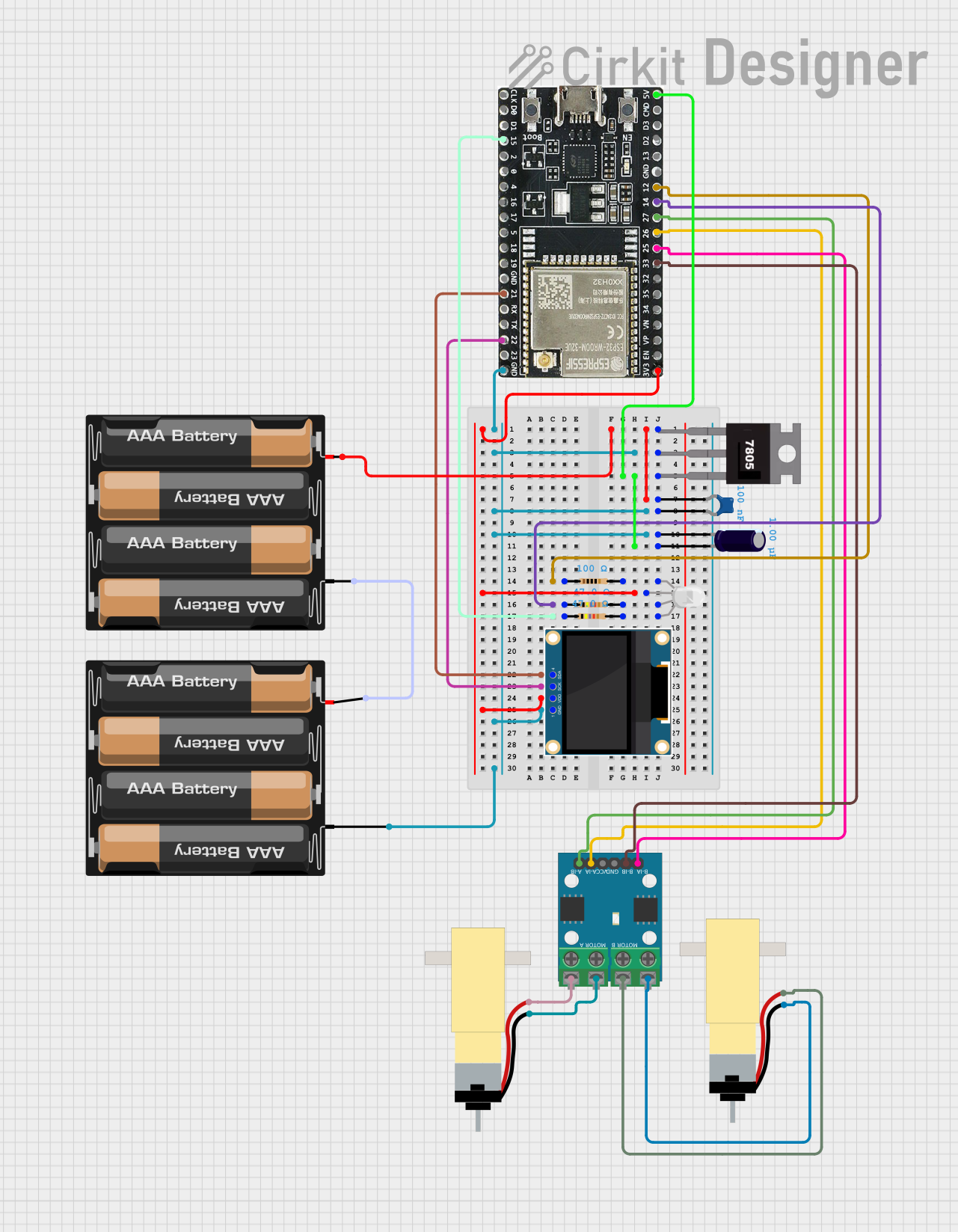
Circuit Documentation
Summary
This circuit is designed to control a pair of hobby gearmotors and an RGB LED using an ESP32 microcontroller. It also includes a 0.96" OLED display for visual feedback and a 7805 voltage regulator to ensure stable power supply. The circuit is powered by a 4 x AAA battery mount.
Component List
Hobby Gearmotor with 48:1 gearbox
- Pins: pin 1, pin 2
- Description: A small DC motor with a 48:1 gearbox for increased torque.
- Purpose: Used for driving the wheels of the robot.
0.96" OLED
- Pins: GND, VDD, SCK, SDA
- Description: A small OLED display for visual feedback.
- Purpose: Displays status messages and other information.
RGB LED (Wokwi compatible)
- Pins: R, COM, G, B
- Description: An RGB LED for visual indicators.
- Purpose: Provides visual feedback using different colors.
4 x AAA Battery Mount
- Pins: -, +
- Description: Battery holder for four AAA batteries.
- Purpose: Powers the entire circuit.
Ceramic Capacitor
- Pins: pin0, pin1
- Description: A capacitor with a capacitance of 0.1 µF.
- Purpose: Used for filtering and stabilizing the voltage.
Resistor (100 Ohms)
- Pins: pin1, pin2
- Description: A resistor with a resistance of 100 Ohms.
- Purpose: Current limiting for the RGB LED.
Resistor (47 Ohms)
- Pins: pin1, pin2
- Description: A resistor with a resistance of 47 Ohms.
- Purpose: Current limiting for the RGB LED.
7805 Voltage Regulator
- Pins: Vin, Gnd, Vout
- Description: A voltage regulator that outputs 5V.
- Purpose: Provides a stable 5V supply to the circuit.
L9110 Motor Driver
- Pins: MOTOR B-A, MOTOR B-B, MOTOR A-A, MOTOR A-B, B-IA, B-IB, GND, VCC, A-IA, A-IB
- Description: A motor driver for controlling two DC motors.
- Purpose: Drives the hobby gearmotors.
Electrolytic Capacitor
- Pins: -, +
- Description: A capacitor with a capacitance of 1 µF.
- Purpose: Used for filtering and stabilizing the voltage.
ESP32-WROOM-32UE
- Pins: 3v3, EN, VP, VN, 34, 35, 32, 33, 25, 26, 27, 14, 12, GND, 13, D2, D3, 5V, 23, 22, TX, RX, 21, 19, 18, 5, 17, 16, 4, 0, 2, 15, D1, D0, CKL
- Description: A powerful microcontroller with WiFi and Bluetooth capabilities.
- Purpose: Controls the entire circuit and handles communication.
Wiring Details
Hobby Gearmotor with 48:1 gearbox
- pin 1 connected to L9110 MOTOR B-B
- pin 2 connected to L9110 MOTOR B-A
0.96" OLED
- GND connected to Common Ground
- VDD connected to ESP32 3v3
- SCK connected to ESP32 22
- SDA connected to ESP32 21
RGB LED (Wokwi compatible)
- R connected to Resistor (100 Ohms) pin2
- COM connected to ESP32 3v3
- G connected to Resistor (47 Ohms) pin2
- B connected to Resistor (47 Ohms) pin2
4 x AAA Battery Mount
- - connected to Common Ground
- + connected to 7805 Vin
Ceramic Capacitor
- pin0 connected to 7805 Vin
- pin1 connected to Common Ground
Resistor (100 Ohms)
- pin1 connected to ESP32 12
- pin2 connected to RGB LED R
Resistor (47 Ohms)
- pin1 connected to ESP32 14
- pin2 connected to RGB LED G
Resistor (47 Ohms)
- pin1 connected to ESP32 15
- pin2 connected to RGB LED B
7805 Voltage Regulator
- Vin connected to 4 x AAA Battery Mount +
- Gnd connected to Common Ground
- Vout connected to ESP32 5V
L9110 Motor Driver
- MOTOR B-A connected to Hobby Gearmotor pin 2
- MOTOR B-B connected to Hobby Gearmotor pin 1
- MOTOR A-A connected to Hobby Gearmotor pin 2
- MOTOR A-B connected to Hobby Gearmotor pin 1
- B-IA connected to ESP32 25
- B-IB connected to ESP32 33
- A-IA connected to ESP32 26
- A-IB connected to ESP32 27
- GND connected to Common Ground
- VCC connected to ESP32 5V
Electrolytic Capacitor
- - connected to Common Ground
- + connected to 7805 Vout
ESP32-WROOM-32UE
- 3v3 connected to Common Ground
- GND connected to Common Ground
- 5V connected to 7805 Vout
- 12 connected to Resistor (100 Ohms) pin1
- 14 connected to Resistor (47 Ohms) pin1
- 15 connected to Resistor (47 Ohms) pin1
- 21 connected to 0.96" OLED SDA
- 22 connected to 0.96" OLED SCK
- 25 connected to L9110 B-IA
- 26 connected to L9110 A-IA
- 27 connected to L9110 A-IB
- 33 connected to L9110 B-IB
Code Documentation
#include <WiFi.h>  //remember to download library
#include <Adafruit_SSD1306.h>

// Define pins for RGB LED and motor driver
#define RED_PIN 14
#define GREEN_PIN 12
#define BLUE_PIN 13
#define MOTOR_A1 26
#define MOTOR_A2 27
#define MOTOR_B1 25
#define MOTOR_B2 33
#define OLED_RESET -1

// Create an object for OLED
Adafruit_SSD1306 display(128, 64, &Wire, OLED_RESET);

// WiFi settings
const char* ssid = "Your_SSID";
const char* password = "Your_PASSWORD";

WiFiServer server(80);

void setup() {
  // Initialize RGB LED pins
  pinMode(RED_PIN, OUTPUT);
  pinMode(GREEN_PIN, OUTPUT);
  pinMode(BLUE_PIN, OUTPUT);

  // Initialize OLED
  if (!display.begin(SSD1306_I2C_ADDRESS, 0x3C)) {
    Serial.println(F("OLED initialization failed"));
    for (;;);
  }

  // Initialize serial communication
  Serial.begin(115200);

  // Set motor driver pins as output
  pinMode(MOTOR_A1, OUTPUT);
  pinMode(MOTOR_A2, OUTPUT);
  pinMode(MOTOR_B1, OUTPUT);
  pinMode(MOTOR_B2, OUTPUT);

  // Display "turned on" message and green light
  display.clearDisplay();
  display.setTextSize(2);
  display.setTextColor(SSD1306_WHITE);
  display.setCursor(10, 25);
  display.println("TURNED ON");
  display.display();
  setRGBColor(0, 255, 0); // Green
  delay(3000);

  // Connect to WiFi
  display.clearDisplay();
  display.setTextSize(1);
  display.setCursor(0, 0);
  display.println("Connecting to WiFi...");
  display.display();

  WiFi.begin(ssid, password);
  while (WiFi.status() != WL_CONNECTED) {
    flashBlue(); // Indicate no connection with flashing blue
    delay(500);
  }

  // Display connected message and set blue light
  display.clearDisplay();
  display.setTextSize(2);
  display.setCursor(10, 25);
  display.println("CONNECTED");
  display