
Circuit Documentation
Summary of the Circuit
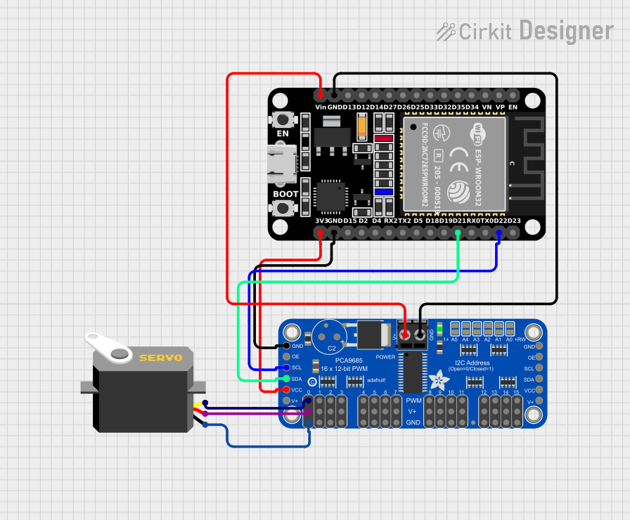
This circuit is designed to control a servo motor using an ESP32 microcontroller and an Adafruit PCA9685 PWM Servo Breakout board. The ESP32 communicates with the PCA9685 via I2C protocol, using its SDA and SCL lines. The PCA9685 is capable of driving multiple servos with its PWM outputs, but in this circuit, only one servo is connected to the first PWM output channel (PWM0). The servo is powered by the 5V output from the PCA9685 board, and the ESP32 provides the logic power for the PCA9685 via its 3.3V output.
Component List
ESP32 (30 pin)
- Description: A microcontroller with Wi-Fi and Bluetooth capabilities, featuring a wide range of GPIO pins.
- Pins: EN, VP, VN, D34, D35, D32, D33, D25, D26, D27, D14, D12, D13, GND, Vin, D23, D22, TX0, RX0, D21, D19, D18, D5, TX2, RX2, D4, D2, D15, 3V3
Servo
- Description: An electromechanical device that can rotate to a specified position using a control signal.
- Pins: gnd, vcc, pulse
Adafruit PCA9685 PWM Servo Breakout
- Description: A 16-channel, 12-bit PWM Fm+ I2C-bus LED controller optimized for driving servos.
- Pins: 5.0V, GND, PWRIN, PWM7, PWM6, PWM5, PWM4, PWM3, PWM2, PWM1, PWM0, VCC, SDA, SCL, OE, PWM15, PWM14, PWM13, PWM12, PWM11, PWM10, PWM9, PWM8
Wiring Details
ESP32 (30 pin)
- GND connected to Adafruit PCA9685 PWM Servo Breakout GND
- Vin connected to Adafruit PCA9685 PWM Servo Breakout PWRIN
- D22 (SCL) connected to Adafruit PCA9685 PWM Servo Breakout SCL
- D21 (SDA) connected to Adafruit PCA9685 PWM Servo Breakout SDA
- 3V3 connected to Adafruit PCA9685 PWM Servo Breakout VCC
Servo
- gnd connected to Adafruit PCA9685 PWM Servo Breakout GND
- vcc connected to Adafruit PCA9685 PWM Servo Breakout 5.0V
- pulse connected to Adafruit PCA9685 PWM Servo Breakout PWM0
Adafruit PCA9685 PWM Servo Breakout
- GND connected to ESP32 GND and Servo gnd
- PWRIN connected to ESP32 Vin
- VCC connected to ESP32 3V3
- SDA connected to ESP32 D21
- SCL connected to ESP32 D22
- 5.0V connected to Servo vcc
- PWM0 connected to Servo pulse
Documented Code
ESP32 Microcontroller Code
#include <Wire.h>
#include <Adafruit_PCA9685.h>

// Create a PCA9685 object
Adafruit_PCA9685 pwm = Adafruit_PCA9685();

void setup() {
  // Initialize the PCA9685
  pwm.begin();

  // Set the PWM frequency to 60 Hz (standard for servos)
  pwm.setPWMFreq(60);
}

void loop() {
  // Move the servo to 0 degrees
  pwm.setPWM(0, 0, servoAngleToPWM(0));
  delay(1000); // Wait for 1 second

  // Move the servo to 90 degrees
  pwm.setPWM(0, 0, servoAngleToPWM(90));
  delay(1000); // Wait for 1 second

  // Move the servo to 180 degrees
  pwm.setPWM(0, 0, servoAngleToPWM(180));
  delay(1000); // Wait for 1 second
}

// Function to convert angle to PWM value
int servoAngleToPWM(int angle) {
  // Convert the angle to a value between 0 and 4095
  // 0 degrees corresponds to approximately 150, 90 degrees to 375, and 180 degrees to 600
  int pulse = map(angle, 0, 180, 150, 600);
  return pulse;
}
Adafruit PCA9685 PWM Servo Breakout Code
The Adafruit PCA9685 PWM Servo Breakout is controlled by the ESP32 microcontroller through the I2C protocol. The code for the ESP32 includes the necessary functions to operate the PCA9685 and control the connected servo. There is no separate code for the PCA9685 itself, as it is an I2C slave device.
Servo Code
The servo does not have code of its own; it is controlled by the PWM signals generated by the PCA9685, which are in turn controlled by the ESP32 microcontroller using the provided code.