
Raspberry Pi 5-Based OCR and Weighing System with Wi-Fi Connectivity
View and Edit Project In Cirkit Designer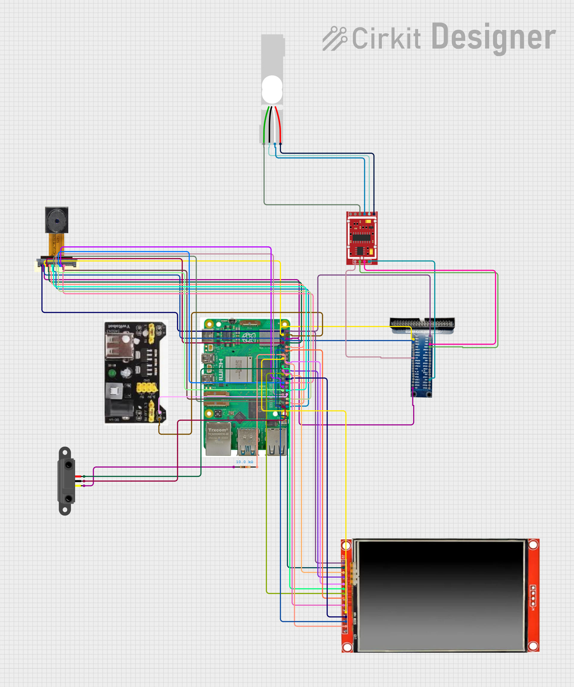
Circuit Documentation
Summary
This circuit is designed to interface a Raspberry Pi 5 microcontroller with various peripherals including an OV2640 Camera Module, an ILI9488 TFT screen, an Infrared Proximity Sensor, a Load Cell, and an HX711 Weighing Sensor Module. The system captures images using the camera, performs Optical Character Recognition (OCR) to extract text, and displays the extracted text on the TFT screen. The IR sensor triggers the camera when a piece of paper is detected for 5 seconds. The load cell data is displayed on the screen, and manual entry is possible via a keypad. Data can be exported via WiFi to an external website.
Component List
Raspberry Pi 5
- Description: A powerful microcontroller with multiple GPIO pins, USB ports, and other interfaces.
- Pins: Type-C, Micro HDMI 1, Micro HDMI 2, Camera 1, Camera 2, PoE, Fan, PCIe, USB 3.0, USB 2.0, Ethernet, 5V, GND, 3.3v, GPIO 14, GPIO 15, GPIO 18, GPIO 23, GPIO 24, GPIO 25, GPIO 8, GPIO 7, GPIO 1, GPIO 12, GPIO 16, GPIO 20, GPIO 21, GPIO 2, GPIO 3, GPIO 4, GPIO 17, GPIO 27, GPIO 22, GPIO 10, GPIO 9, GPIO 11, GPIO 0, GPIO 5, GPIO 6, GPIO 13, GPIO 19, GPIO 26
OV2640 Camera Module
- Description: A camera module used for capturing images.
- Pins: 3.3V, GND, SIOC, SIOD, VSync, HRef, PCLK, XCLK, D9, D8, D7, D6, D5, D4, D3, D2, RET, PWDN
MB102 Breadboard Power Supply Module 3.3V/5V
- Description: A power supply module that provides 3.3V and 5V outputs.
- Pins: GND, 3.3V, 5v
LCD TFT screen ILI9488 HD
- Description: A high-definition TFT screen for displaying text and images.
- Pins: PEN, TDO, TDI, VCC (3.3~5V), GND, CS, RST, D/C, SDI(MOSI), SCK, BL, SDO(MISO), TCS, TCK
Infrared Proximity Sensor
- Description: A sensor used to detect the presence of objects.
- Pins: Vout, GND, Vcc
Resistor
- Description: A resistor with a resistance of 10k Ohms.
- Pins: pin1, pin2
- Properties: Resistance: 10000 Ohms
GPIO Expander
- Description: A module used to expand the number of GPIO pins.
- Pins: 5v, GND, 5V, TXD, RXD, GPIO18, GPIO23, GPIO24, GPIO25, CE0, CE1, EEC, GPIO12, GPIO16, GPIO20, GPIO21, GPIO26, GPIO19, GPIO13, GPIO6, GPIO5, EED, SCLK, MISO, MOSI, 3V3, GPIO22, GPIO27, GPIO17, GPIO4, SCL, SDA
Load Cell - Red/white/black/green
- Description: A load cell used for measuring weight.
- Pins: E+, A-, E-, A+
HX711 Weighing Sensor Module
- Description: A module used to interface with the load cell for weight measurement.
- Pins: B-, B+, A-, A+, E-, E+, VCC, CK/TX, DO/RX, GND
Wiring Details
Raspberry Pi 5
- 5V: Connected to GPIO Expander (5v), LCD TFT screen ILI9488 HD (VCC (3.3~5V)), MB102 Breadboard Power Supply Module 3.3V/5V (5v)
- GND: Connected to GPIO Expander (GND), OV2640 Camera Module (GND), Infrared Proximity Sensor (GND), MB102 Breadboard Power Supply Module 3.3V/5V (GND), LCD TFT screen ILI9488 HD (GND)
- 3.3v: Connected to OV2640 Camera Module (3.3V), Infrared Proximity Sensor (Vcc)
- GPIO 14: Connected to OV2640 Camera Module (HRef)
- GPIO 15: Connected to OV2640 Camera Module (PCLK)
- GPIO 18: Connected to LCD TFT screen ILI9488 HD (BL)
- GPIO 24: Connected to LCD TFT screen ILI9488 HD (D/C)
- GPIO 25: Connected to LCD TFT screen ILI9488 HD (RST)
- GPIO 8: Connected to LCD TFT screen ILI9488 HD (CS)
- GPIO 7: Connected to LCD TFT screen ILI9488 HD (TCS)
- GPIO 1: Connected to OV2640 Camera Module (PWDN)
- GPIO 12: Connected to OV2640 Camera Module (D9)
- GPIO 16: Connected to OV2640 Camera Module (D6)
- GPIO 21: Connected to OV2640 Camera Module (D8)
- GPIO 2: Connected to GPIO Expander (SDA), OV2640 Camera Module (SIOD)
- GPIO 3: Connected to GPIO Expander (SCL), OV2640 Camera Module (SIOC)
- GPIO 4: Connected to OV2640 Camera Module (VSync)
- GPIO 17: Connected to LCD TFT screen ILI9488 HD (TDI)
- GPIO 27: Connected to LCD TFT screen ILI9488 HD (TDO), Resistor (pin2)
- GPIO 22: Connected to LCD TFT screen ILI9488 HD (TCK)
- GPIO 10: Connected to LCD TFT screen ILI9488 HD (SDI(MOSI))
- GPIO 9: Connected to LCD TFT screen ILI9488 HD (SDO(MISO))
- GPIO 11: Connected to LCD TFT screen ILI9488 HD (SCK)
- GPIO 0: Connected to OV2640 Camera Module (D3)
- GPIO 5: Connected to OV2640 Camera Module (D2)
- GPIO 6: Connected to OV2640 Camera Module (D4)
- GPIO 13: Connected to OV2640 Camera Module (D5)
- GPIO 19: Connected to OV2640 Camera Module (RET)
- GPIO 26: Connected to OV2640 Camera Module (D7)
OV2640 Camera Module
- 3.3V: Connected to Raspberry Pi 5 (3.3v)
- GND: Connected to Raspberry Pi 5 (GND)
- SIOC: Connected to GPIO Expander (SCL), Raspberry Pi 5 (GPIO 3)
- SIOD: Connected to GPIO Expander (SDA), Raspberry Pi 5 (GPIO 2)
- VSync: Connected to Raspberry Pi 5 (GPIO 4)
- HRef: Connected to Raspberry Pi 5 (GPIO 14)
- PCLK: Connected to Raspberry Pi 5 (GPIO 15)
- PWDN: Connected to Raspberry Pi 5 (GPIO 1)
- D9: Connected to Raspberry Pi 5 (GPIO 12)
- D8: Connected to Raspberry Pi 5 (GPIO 21)
- D7: Connected to Raspberry Pi 5 (GPIO 26)
- D6: Connected to Raspberry Pi 5 (GPIO 16)
- D5: Connected to Raspberry Pi 5 (GPIO 13)
- D4: Connected to Raspberry Pi 5 (GPIO 6)
- D3: Connected to Raspberry Pi 5 (GPIO 0)
- D2: Connected to Raspberry Pi 5 (GPIO 5)
- RET: Connected to Raspberry Pi 5 (GPIO 19)
MB102 Breadboard Power Supply Module 3.3V/5V
- 5v: Connected to Raspberry Pi 5 (5V)
- GND: Connected to Raspberry Pi 5 (GND)
LCD TFT screen ILI9488 HD
- VCC (3.3~5V): Connected to Raspberry Pi 5 (5V)
- GND: Connected to Raspberry Pi 5 (GND)
- CS: Connected to Raspberry Pi 5 (GPIO 8)
- RST: Connected to Raspberry Pi 5 (GPIO 25)
- D/C: Connected to Raspberry Pi 5 (GPIO 24)
- SDI(MOSI): Connected to Raspberry Pi 5 (GPIO 10)
- SCK: Connected to Raspberry Pi 5 (GPIO 11)
- BL: Connected to Raspberry Pi 5 (GPIO 18)
- SDO(MISO): Connected to Raspberry Pi 5 (GPIO 9)
- **