
Battery-Powered ESP32-CAM Surveillance System with Step-Up Converter
View and Edit Project In Cirkit Designer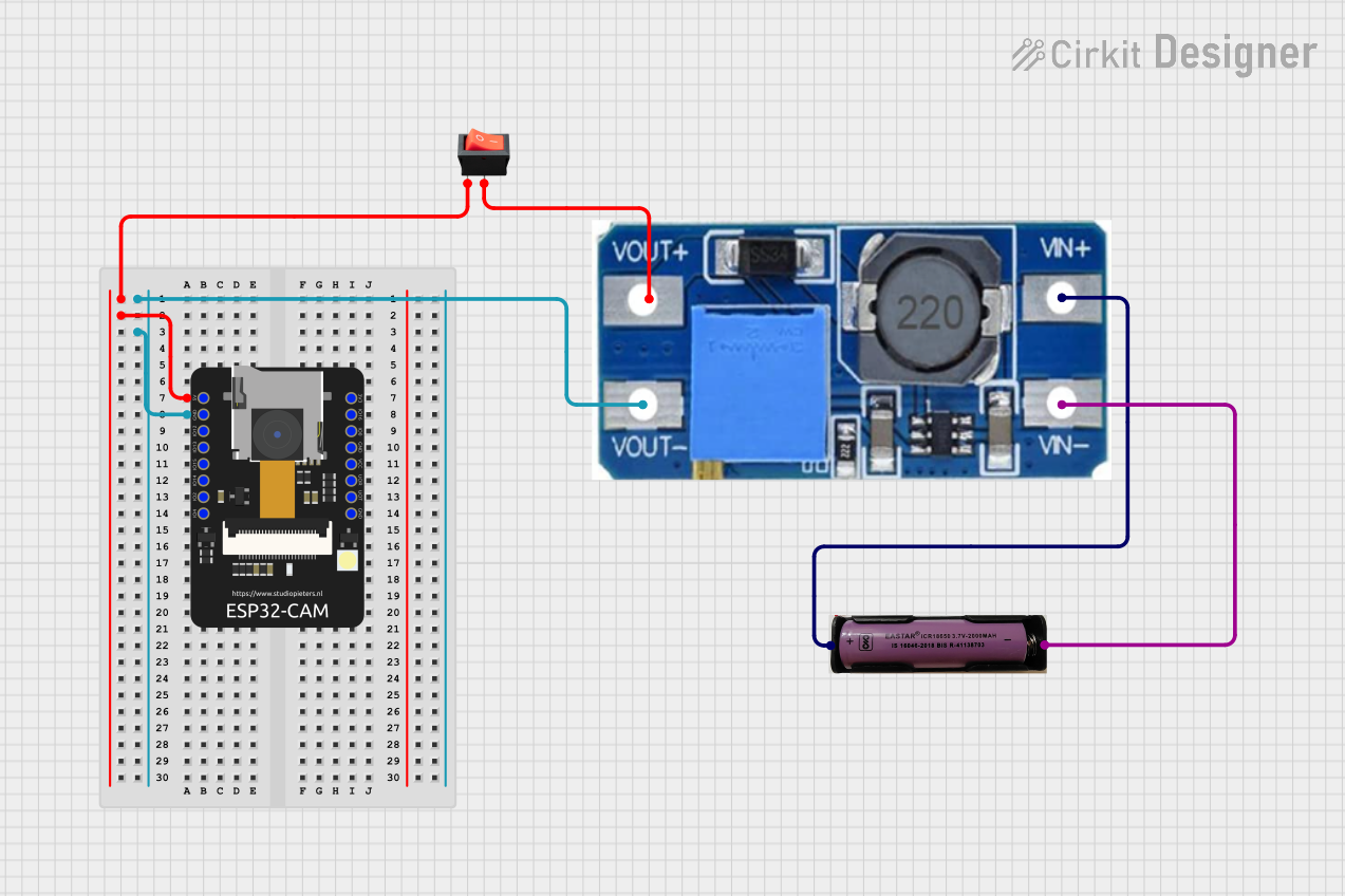
Circuit Documentation
Summary
This document provides a detailed overview of a circuit that includes an ESP32-CAM module, a 3.7V battery, a step-up boost power converter, and a rocker switch. The circuit is designed to power the ESP32-CAM using a 3.7V battery, with the voltage being stepped up to the required level by the power converter. The rocker switch is used to control the power supply to the ESP32-CAM.
Component List
ESP32-CAM
- Description: A low-cost development board with a camera module, suitable for IoT applications.
- Pins: 5V, GND, IO12, IO13, IO15, IO14, IO2, IO4, VOT, VOR, VCC, IO0, IO16, 3V3
3.7V Battery
- Description: A rechargeable lithium-ion battery.
- Pins: +, -
Step Up Boost Power Converter, Adjustable Voltage Regulator
- Description: A power converter that steps up the input voltage to a higher, adjustable output voltage.
- Pins: VOUT+, VOUT-, VIN+, VIN-
Rocker Switch
- Description: A simple on/off switch used to control the power supply.
- Pins: input, output
Wiring Details
ESP32-CAM
5V Pin:
- Connected to the input pin of the rocker switch.
GND Pin:
- Connected to the VOUT- pin of the Step Up Boost Power Converter.
3.7V Battery
+ Pin:
- Connected to the VIN+ pin of the Step Up Boost Power Converter.
- Pin:
- Connected to the VIN- pin of the Step Up Boost Power Converter.
Step Up Boost Power Converter, Adjustable Voltage Regulator
VOUT+ Pin:
- Connected to the output pin of the rocker switch.
VOUT- Pin:
- Connected to the GND pin of the ESP32-CAM.
VIN+ Pin:
- Connected to the + pin of the 3.7V Battery.
VIN- Pin:
- Connected to the - pin of the 3.7V Battery.
Rocker Switch
input Pin:
- Connected to the 5V pin of the ESP32-CAM.
output Pin:
- Connected to the VOUT+ pin of the Step Up Boost Power Converter.
Code
There is no code provided for this circuit.
This document provides a comprehensive overview of the circuit, including a summary, detailed component list, wiring details, and code documentation. This should serve as a useful reference for understanding and replicating the circuit.