
Battery-Powered LED Control System with Push Switches and Boost Converter
View and Edit Project In Cirkit Designer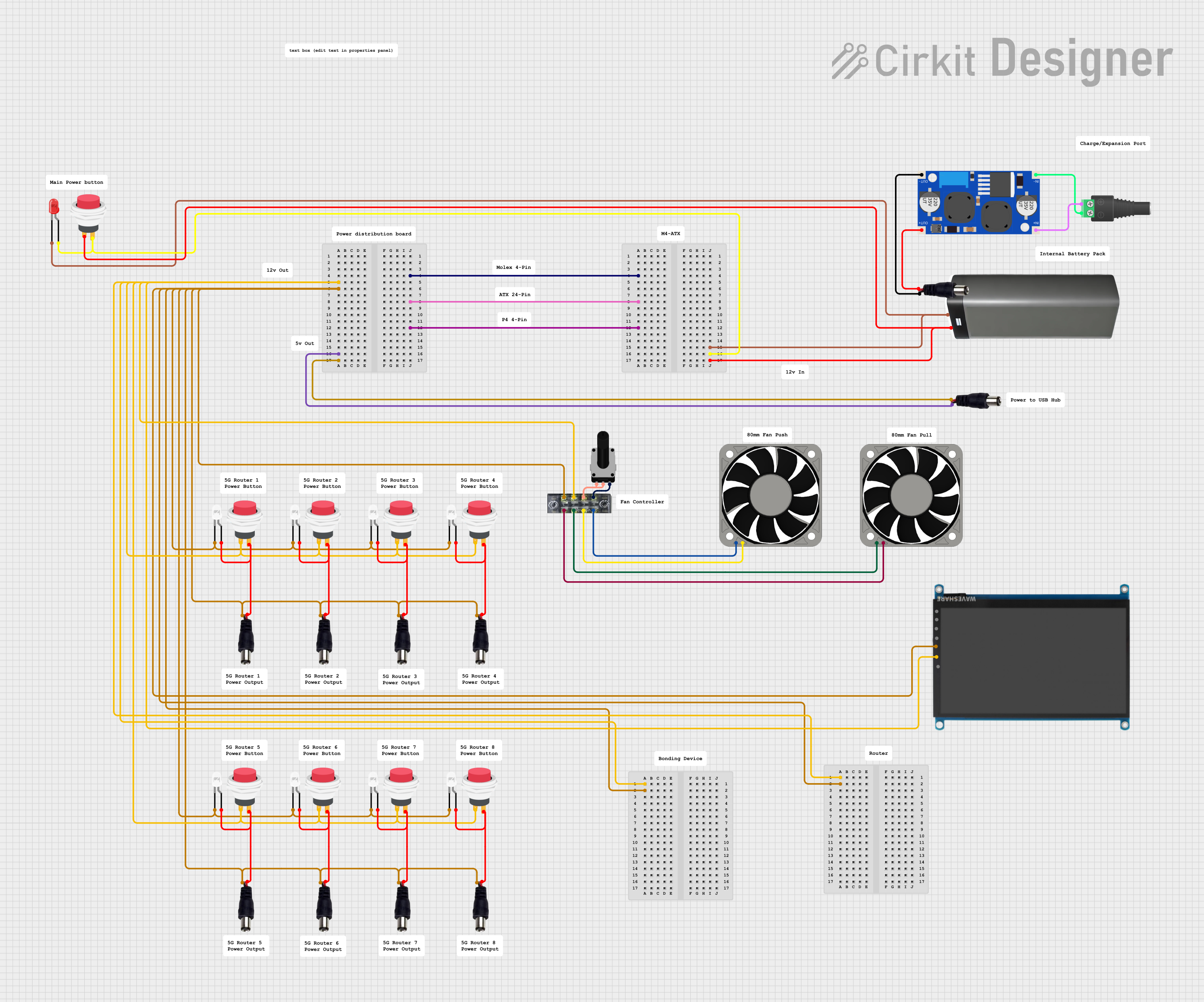
Circuit Documentation
Summary
This circuit consists of multiple LEDs, power jacks, push switches, a battery pack, a boost converter, a rotary potentiometer, and a 7-inch WaveShare display. The circuit is designed to control the power and illumination of the LEDs through push switches and to power the display and fans using a boost converter and a battery pack.
Component List
LED: Two Pin (red)
- Pins: cathode, anode
- Description: Red LED
- Purpose: Provides red illumination
LED: Two Pin (white)
- Pins: cathode, anode
- Description: White LED
- Purpose: Provides white illumination
Power Jack
- Pins: POSITIF, NEGATIF
- Description: Standard power jack
- Purpose: Provides power input
2Pin Push Switch
- Pins: Input +, Output +
- Description: Push button switch
- Purpose: Controls the power to the LEDs
Battery Pack
- Pins: +, -
- Description: Battery pack
- Purpose: Provides power to the circuit
2.1mm Barrel Jack with Terminal Block
- Pins: POS, NEG
- Description: Barrel jack with terminal block
- Purpose: Connects to the boost converter
XL6009E1 Boost Converter
- Pins: IN+, IN-, OUT-, OUT+
- Description: Boost converter
- Purpose: Boosts the voltage from the battery pack
40 Fan 12v
- Pins: +12V, -12V
- Description: 12V fan
- Purpose: Provides cooling
Rotary Potentiometer
- Pins: leg1, wiper, leg2
- Description: Potentiometer
- Purpose: Adjusts resistance
7 inch WaveShare (H)
- Pins: HDMI, +, -, USB Power, Touch USB, Audio, VGA
- Description: 7-inch display
- Purpose: Displays visual output
Terminal Block
- Pins: 1, 2, 3, 4, 5, 6, 7, 8
- Description: Terminal block
- Purpose: Connects multiple components
Wiring Details
LED: Two Pin (red)
- cathode: Connected to the negative terminal of the battery pack
- anode: Connected to the output of a push switch
LED: Two Pin (white)
- cathode: Connected to the negative terminal of the power jack
- anode: Connected to the output of a push switch
Power Jack
- POSITIF: Connected to the anode of the white LEDs
- NEGATIF: Connected to the cathode of the white LEDs
2Pin Push Switch
- Input +: Connected to the positive terminal of the power jack
- Output +: Connected to the anode of the LEDs
Battery Pack
- +: Connected to the input of a push switch
- -: Connected to the cathode of the red LED
2.1mm Barrel Jack with Terminal Block
- POS: Connected to the input of the boost converter
- NEG: Connected to the input of the boost converter
XL6009E1 Boost Converter
- IN+: Connected to the positive terminal of the barrel jack
- IN-: Connected to the negative terminal of the barrel jack
- OUT+: Connected to the positive terminal of the power jack
- OUT-: Connected to the negative terminal of the power jack
40 Fan 12v
- +12V: Connected to the terminal block
- -12V: Connected to the terminal block
Rotary Potentiometer
- leg1: Connected to the terminal block
- wiper: Connected to the terminal block
- leg2: Connected to the terminal block
7 inch WaveShare (H)
- +: Connected to the terminal block
- -: Connected to the terminal block
Terminal Block
- 1: Connected to the negative terminal of the power jack
- 2: Connected to the negative terminal of the fan
- 3: Connected to the positive terminal of the display
- 4: Connected to the positive terminal of the fan
- 5: Connected to the potentiometer leg1 and wiper
- 6: Connected to the negative terminal of the fan
- 7: Connected to the potentiometer leg2
- 8: Connected to the positive terminal of the fan
Code
No microcontroller code is provided for this circuit.
This documentation provides a comprehensive overview of the circuit, including a summary, component list, wiring details, and code documentation. Each component is described with its purpose and connections, ensuring clarity and ease of understanding for anyone working with this circuit.