
ESP32-Based Automated Landing Gear System with Ultrasonic Sensor and LCD Display
View and Edit Project In Cirkit Designer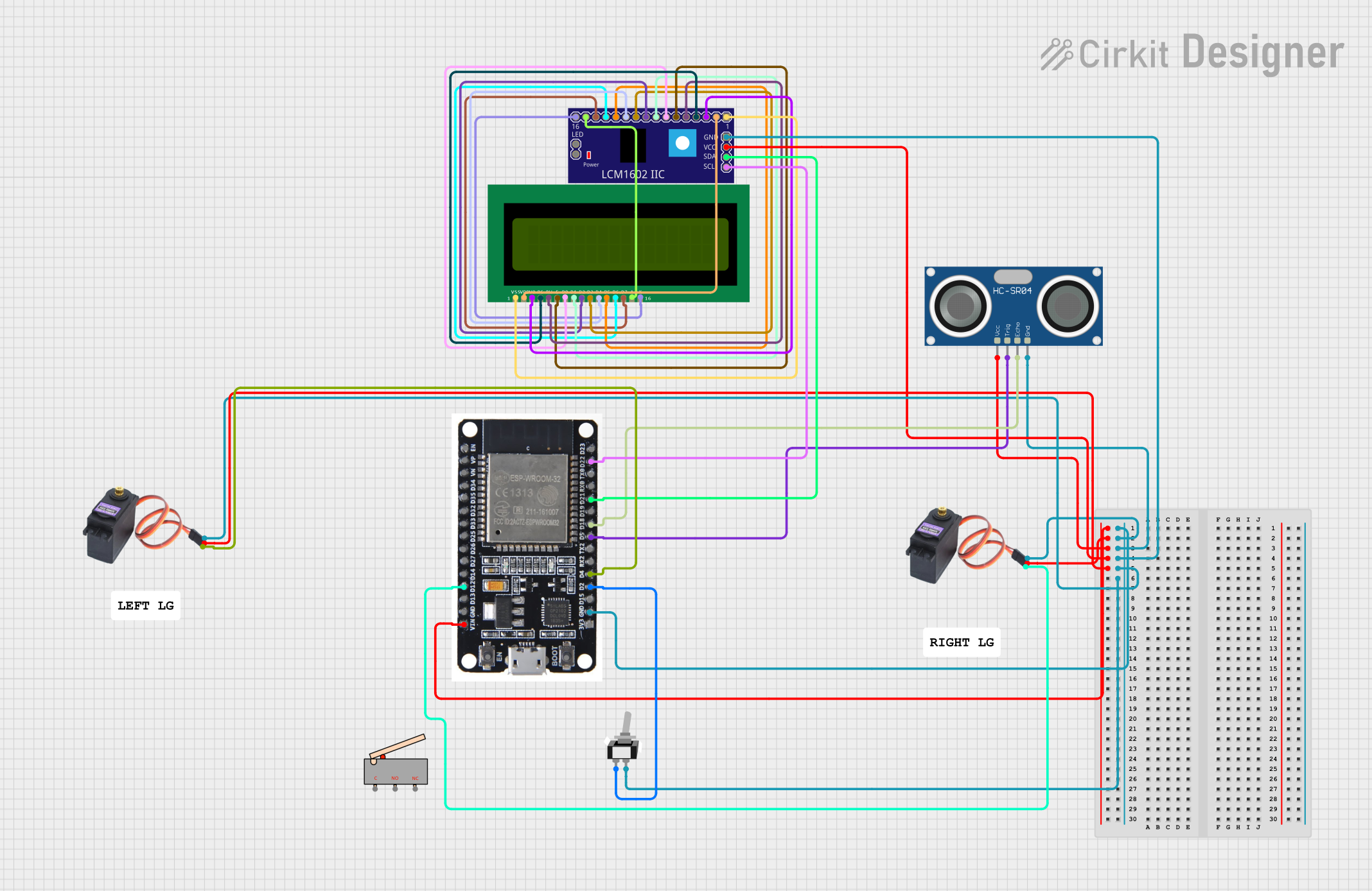
Circuit Documentation
Summary
This circuit is designed to control a landing gear system using an ESP32 microcontroller. The system includes an ultrasonic sensor to measure distance, a toggle switch for manual control, two servos to actuate the landing gear, and a 16x2 LCD display to show the status and distance measurements. The components are interconnected to achieve the desired functionality, and the ESP32 is programmed to manage the operations.
Component List
16X2 LCD
- Description: A 16x2 character LCD display.
- Pins: VSS, VDD, V0, RS, RW, E, D1, D0, D2, D3, D4, D6, D5, D7, A, K
Toggle Switch SPST
- Description: A single-pole single-throw toggle switch.
- Pins: L1, COM
HC-SR04 Ultrasonic Sensor
- Description: An ultrasonic distance sensor.
- Pins: VCC, TRIG, ECHO, GND
MG996R Servo Motor (2 units)
- Description: A high-torque servo motor.
- Pins: GND, VCC, SIG
Limit Switch
- Description: A mechanical limit switch.
- Pins: C, NO, NC
ESP32
- Description: A powerful microcontroller with Wi-Fi and Bluetooth capabilities.
- Pins: EN, VP, VN, D34, D35, D32, D33, D25, D26, D27, D14, D12, D13, GND, VIN, 3V3, D15, D2, D4, RX2, TX2, D5, D18, D19, D21, RX0, TX0, D22, D23, BOOT
LCM1602 IIC
- Description: An I2C interface for the 16x2 LCD display.
- Pins: GND, VCC, SDA, SCL, D6, D7, A, K, VSS, VDD, V0, RS, D2, D3, D4, D5, RW, E, D0, D1, LED_A, LED_B
Wiring Details
16X2 LCD
- VSS connected to LCM1602 IIC VSS
- VDD connected to LCM1602 IIC VDD
- V0 connected to LCM1602 IIC V0
- RS connected to LCM1602 IIC RS
- RW connected to LCM1602 IIC RW
- E connected to LCM1602 IIC E
- D1 connected to LCM1602 IIC D1
- D0 connected to LCM1602 IIC D0
- D2 connected to LCM1602 IIC D2
- D3 connected to LCM1602 IIC D3
- D4 connected to LCM1602 IIC D4
- D6 connected to LCM1602 IIC D6
- D5 connected to LCM1602 IIC D5
- D7 connected to LCM1602 IIC D7
- A connected to LCM1602 IIC A
- K connected to LCM1602 IIC K
Toggle Switch SPST
- L1 connected to ESP32 D2
- COM connected to GND
HC-SR04 Ultrasonic Sensor
- VCC connected to ESP32 VIN
- TRIG connected to ESP32 D5
- ECHO connected to ESP32 D18
- GND connected to GND
MG996R Servo Motor (1)
- GND connected to GND
- VCC connected to ESP32 VIN
- SIG connected to ESP32 D4
MG996R Servo Motor (2)
- GND connected to GND
- VCC connected to ESP32 VIN
- SIG connected to ESP32 D12
ESP32
- VIN connected to MG996R VCC, HC-SR04 VCC, LCM1602 IIC VCC
- GND connected to MG996R GND, HC-SR04 GND, LCM1602 IIC GND, Toggle Switch COM
- D2 connected to Toggle Switch L1
- D5 connected to HC-SR04 TRIG
- D18 connected to HC-SR04 ECHO
- D4 connected to MG996R SIG
- D12 connected to MG996R SIG
- D21 connected to LCM1602 IIC SDA
- D22 connected to LCM1602 IIC SCL
LCM1602 IIC
- GND connected to GND
- VCC connected to ESP32 VIN
- SDA connected to ESP32 D21
- SCL connected to ESP32 D22
- VSS connected to 16X2 LCD VSS
- VDD connected to 16X2 LCD VDD
- V0 connected to 16X2 LCD V0
- RS connected to 16X2 LCD RS
- RW connected to 16X2 LCD RW
- E connected to 16X2 LCD E
- D1 connected to 16X2 LCD D1
- D0 connected to 16X2 LCD D0
- D2 connected to 16X2 LCD D2
- D3 connected to 16X2 LCD D3
- D4 connected to 16X2 LCD D4
- D6 connected to 16X2 LCD D6
- D5 connected to 16X2 LCD D5
- D7 connected to 16X2 LCD D7
- A connected to 16X2 LCD A
- K connected to 16X2 LCD K
Code Documentation
#include <Wire.h>
#include <LiquidCrystal_I2C.h>
#include <ESP32Servo.h>

// Pin definitions
#define TRIG_PIN 5
#define ECHO_PIN 18
#define SWITCH_PIN 2
#define SERVO1_PIN 4
#define SERVO2_PIN 12
#define I2C_SDA 21
#define I2C_SCL 22

// Create objects
LiquidCrystal_I2C lcd(0x27, 16, 2);
Servo servo1;
Servo servo2;

void setup() {
  // Initialize serial communication
  Serial.begin(115200);

  // Initialize LCD
  lcd.begin(16, 2);
  lcd.backlight();
  lcd.setCursor(0, 0);
  lcd.print("Landing Gear");

  // Initialize ultrasonic sensor pins
  pinMode(TRIG_PIN, OUTPUT);
  pinMode(ECHO_PIN, INPUT);

  // Initialize switch pin
  pinMode(SWITCH_PIN, INPUT);

  // Attach servos
  servo1.attach(SERVO1_PIN);
  servo2.attach(SERVO2_PIN);

  // Set initial servo positions
  servo1.write(0); // Retracted
  servo2.write(0); // Retracted
}

void loop() {
  // Read distance from ultrasonic sensor
  long duration, distance;
  digitalWrite(TRIG_PIN, LOW);
  delayMicroseconds(2);
  digitalWrite(TRIG_PIN, HIGH);
  delayMicroseconds(10);
  digitalWrite(TRIG_PIN, LOW);
  duration = pulseIn(ECHO_PIN, HIGH);
  distance = (duration / 2) / 29.1;

  // Display distance on LCD
  lcd.setCursor(0, 1);
  lcd.print("Dist: ");
  lcd.print(distance);
  lcd.print(" cm");

  // Check switch state
  int switchState = digitalRead(SWITCH_PIN);

  // Control servos based on distance and switch state
  if (switchState == HIGH || distance < 10) {
    // Extend landing gear
    servo1.write(90);
    servo2.write(90);
    lcd.setCursor(0, 1);
    lcd.print("Gear: Extended");
  } else {
    // Retract landing gear
    servo1.write(0);
    servo2.write(0);
    lcd.setCursor(0, 1);
    lcd.print("Gear: Retracted");
  }

  delay(100);
}
This code initializes the components, reads the distance from the ultrasonic sensor, displays the distance on the LCD, and controls the servos based on the distance and the state of the toggle switch. The servos extend or retract the landing gear accordingly.