
Battery-Powered Motor Control System with Adafruit DRV8833 and Toggle Switch
View and Edit Project In Cirkit Designer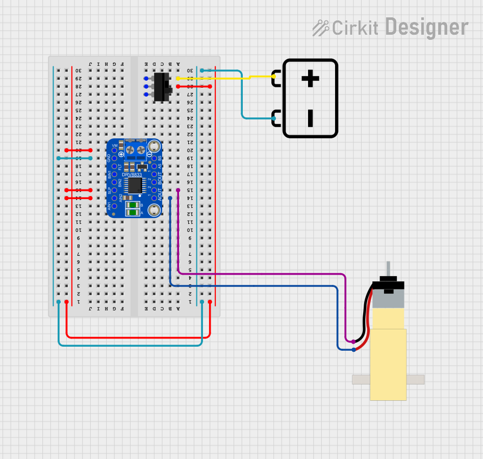
Circuit Documentation
Summary
This circuit is designed to control a hobby gearmotor using an Adafruit DRV8833 DC-Stepper Motor Driver. The motor driver is powered by a 12V battery and controlled via a toggle switch. The toggle switch allows the user to enable or disable the motor driver.
Component List
Adafruit DRV8833 DC-Stepper Motor Driver
- Description: A dual H-bridge motor driver that can drive two DC motors or one stepper motor.
- Pins: AOUT2, AOUT1, BOUT1, BOUT2, ASEN, BSEN, VMOTOR, GND, NFAULT, BIN1, BIN2, !SLEEP, AIN2, AIN1, PWRIN
Hobby Gearmotor with 48:1 gearbox
- Description: A small DC motor with a 48:1 gearbox for increased torque.
- Pins: pin 1, pin 2
Toggle Switch
- Description: A simple on/off switch.
- Pins: L1, COM, L2
12V Battery
- Description: A power source providing 12V.
- Pins: -, +
Wiring Details
Adafruit DRV8833 DC-Stepper Motor Driver
- AIN2 is connected to !SLEEP and VMOTOR of the same motor driver and to COM of the Toggle Switch.
- GND is connected to the - pin of the 12V Battery.
- AOUT1 is connected to pin 2 of the Hobby Gearmotor.
- AOUT2 is connected to pin 1 of the Hobby Gearmotor.
Hobby Gearmotor with 48:1 gearbox
- pin 1 is connected to AOUT2 of the Adafruit DRV8833 DC-Stepper Motor Driver.
- pin 2 is connected to AOUT1 of the Adafruit DRV8833 DC-Stepper Motor Driver.
Toggle Switch
- COM is connected to AIN2, !SLEEP, and VMOTOR of the Adafruit DRV8833 DC-Stepper Motor Driver.
- L1 is connected to the + pin of the 12V Battery.
12V Battery
- + is connected to L1 of the Toggle Switch.
- - is connected to GND of the Adafruit DRV8833 DC-Stepper Motor Driver.
Code
There is no code provided for this circuit.