
ESP32-Based Dual Battery Voltage Monitoring and Automatic Switching System
View and Edit Project In Cirkit Designer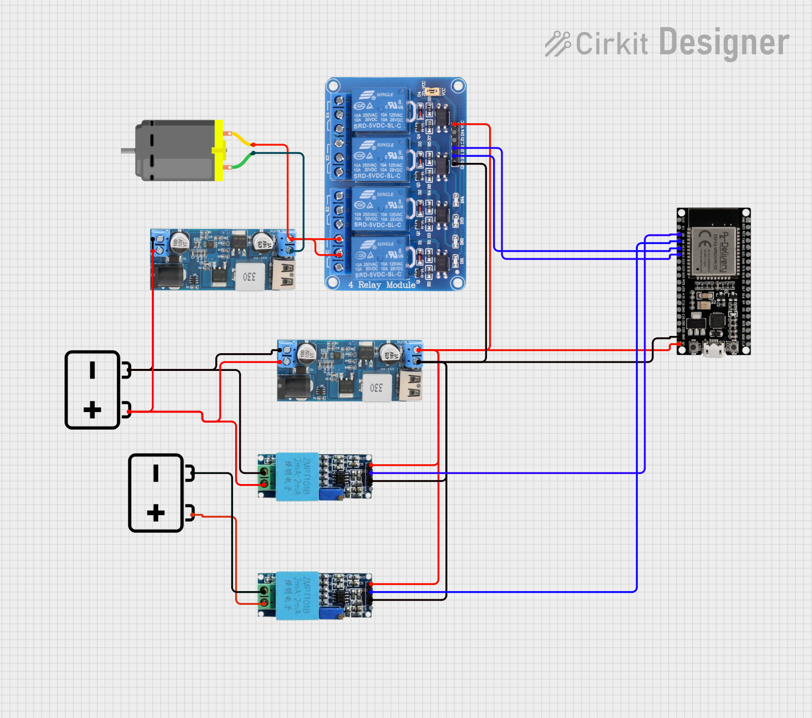
Circuit Documentation
Summary
The circuit is designed to monitor the voltage of two 12v batteries and switch between them based on a voltage threshold using a microcontroller and relay system. The circuit includes voltage sensors to monitor the battery voltages, step-down power converters to provide 5v power to the microcontroller and relays, and a DC motor as the load. The ESP32 microcontroller reads the voltage levels from the sensors and controls the relays to switch the battery connection to the motor.
Component List
12v Battery
- Description: A 12v power source.
- Pins:
-(Negative),+(Positive)
Voltage Sensor
- Description: Measures the voltage level of a circuit.
- Pins:
Ground,Phase,Vcc,Out,Gnd
12v to 5v Step Down Power Converter
- Description: Converts 12v to a stable 5v output.
- Pins:
VIN 9v-36v,VIN+,VIN-,USB OUTPUT 5V,5v OUTPUT,GND
Relay 4 Channel 5v
- Description: A 4-channel relay module that can control up to four circuits.
- Pins:
GND,IN1,IN2,IN3,IN4,VCC,COM1,COM2,COM3,COM4,NO1,NO2,NO3,NO4,NC1,NC2,NC3,NC4
ESP32 38 PINS
- Description: A microcontroller with WiFi and Bluetooth capabilities.
- Pins:
GND,G23,G22,TXD,RXD,G21,G19,G18,G5,G17,G16,G4,G0,G2,G15,SDI,SD0,CLK,3V3,EN,SP,SN,G34,G35,G32,33,G25,G26,G27,G14,G12,G13,SD2,SD3,5V
DC Motor
- Description: A motor that operates on DC power.
- Pins:
pin 1,pin 2
Wiring Details
12v Battery
-(Negative) connected to the negative input of the step-down converters and ground of the voltage sensors.+(Positive) connected to the positive input of the step-down converters and phase of the voltage sensors.
Voltage Sensor
Groundconnected to the negative terminal of the battery.Phaseconnected to the positive terminal of the battery.Vccconnected to the 5v output from the step-down converter.Outconnected to the ESP32 for voltage sensing.Gndconnected to the ground of the circuit.
12v to 5v Step Down Power Converter
VIN 9v-36vconnected to the 12v battery.VIN+connected to the positive terminal of the battery.VIN-connected to the negative terminal of the battery.USB OUTPUT 5Vnot used in this circuit.5v OUTPUTconnected to the Vcc of the voltage sensors, VCC of the relay module, and 5V of the ESP32.GNDconnected to the ground of the circuit.
Relay 4 Channel 5v
GNDconnected to the ground of the circuit.IN1,IN2controlled by the ESP32.VCCconnected to the 5v output from the step-down converter.COM1connected to the 5v output from the second step-down converter.NO1connected to the DC motor.
ESP32 38 PINS
5Vconnected to the 5v output from the step-down converter.GNDconnected to the ground of the circuit.G34,G35connected to the output of the voltage sensors.G23,G22connected to the input of the relay module.
DC Motor
pin 1connected to the ground of the circuit.pin 2connected to the normally open (NO) contact of the relay.
Documented Code
// Pin Definitions
const int sensorPin1 = 34; // Voltage Sensor 1 connected to G34
const int sensorPin2 = 35; // Voltage Sensor 2 connected to G35
const int relayPin1 = 23;  // Relay 1 IN1 connected to G23
const int relayPin2 = 22;  // Relay 2 IN2 connected to G22

// Voltage Threshold
const float voltageThreshold = 11.0; // Threshold voltage in volts

// Calibration Constants (to convert ADC value to voltage)
const float referenceVoltage = 3.3;  // Reference voltage of ESP32 ADC
const int adcMaxValue = 4095;        // Maximum ADC value (12-bit ADC)
const float voltageDividerRatio = 5.0; // Voltage divider ratio of the sensor

void setup() {
  // Initialize Serial Monitor for debugging
  Serial.begin(115200);

  // Initialize relay pins as outputs
  pinMode(relayPin1, OUTPUT);
  pinMode(relayPin2, OUTPUT);

  // Initially, connect Battery 1 to the load and disconnect Battery 2
  digitalWrite(relayPin1, LOW); // LOW means Relay 1 is connected
  digitalWrite(relayPin2, HIGH); // HIGH means Relay 2 is disconnected
}

void loop() {
  // Read the voltage from the sensors
  float voltage1 = readVoltage(sensorPin1);
  float voltage2 = readVoltage(sensorPin2);

  // Print the voltage values for debugging
  Serial.print("Battery 1 Voltage: ");
  Serial.print(voltage1);
  Serial.println(" V");

  Serial.print("Battery 2 Voltage: ");
  Serial.print(voltage2);
  Serial.println(" V");

  // Check if Battery 1 voltage drops below the threshold
  if (voltage1 < voltageThreshold) {
    // Switch to Battery 2
    digitalWrite(relayPin1, HIGH);  // Disconnect Battery 1
    digitalWrite(relayPin2, LOW);   // Connect Battery 2
    Serial.println("Switching to Battery 2...");
  } else {
    // Keep using Battery 1
    digitalWrite(relayPin1, LOW);   // Connect Battery 1
    digitalWrite(relayPin2, HIGH);  // Disconnect Battery 2
    Serial.println("Using Battery 1...");
  }

  // Delay for stability (adjust as needed)
  delay(1000);
}

// Function to read and convert ADC value to voltage
float readVoltage(int sensorPin) {
  int adcValue = analogRead(sensorPin);
  float voltage = (adcValue * referenceVoltage / adcMaxValue) * voltageDividerRatio;
  return voltage;
}
This code is designed to run on an ESP32 microcontroller. It initializes the relay pins and sets up the serial communication for debugging. The loop function reads the voltage from two sensors and switches the relays based on the voltage threshold. The readVoltage function converts the ADC value to a voltage reading, taking into account the reference voltage, ADC resolution, and voltage divider ratio.