Arduino Nano Controlled Clap-Activated Sound and Light System
Circuit Documentation
Summary
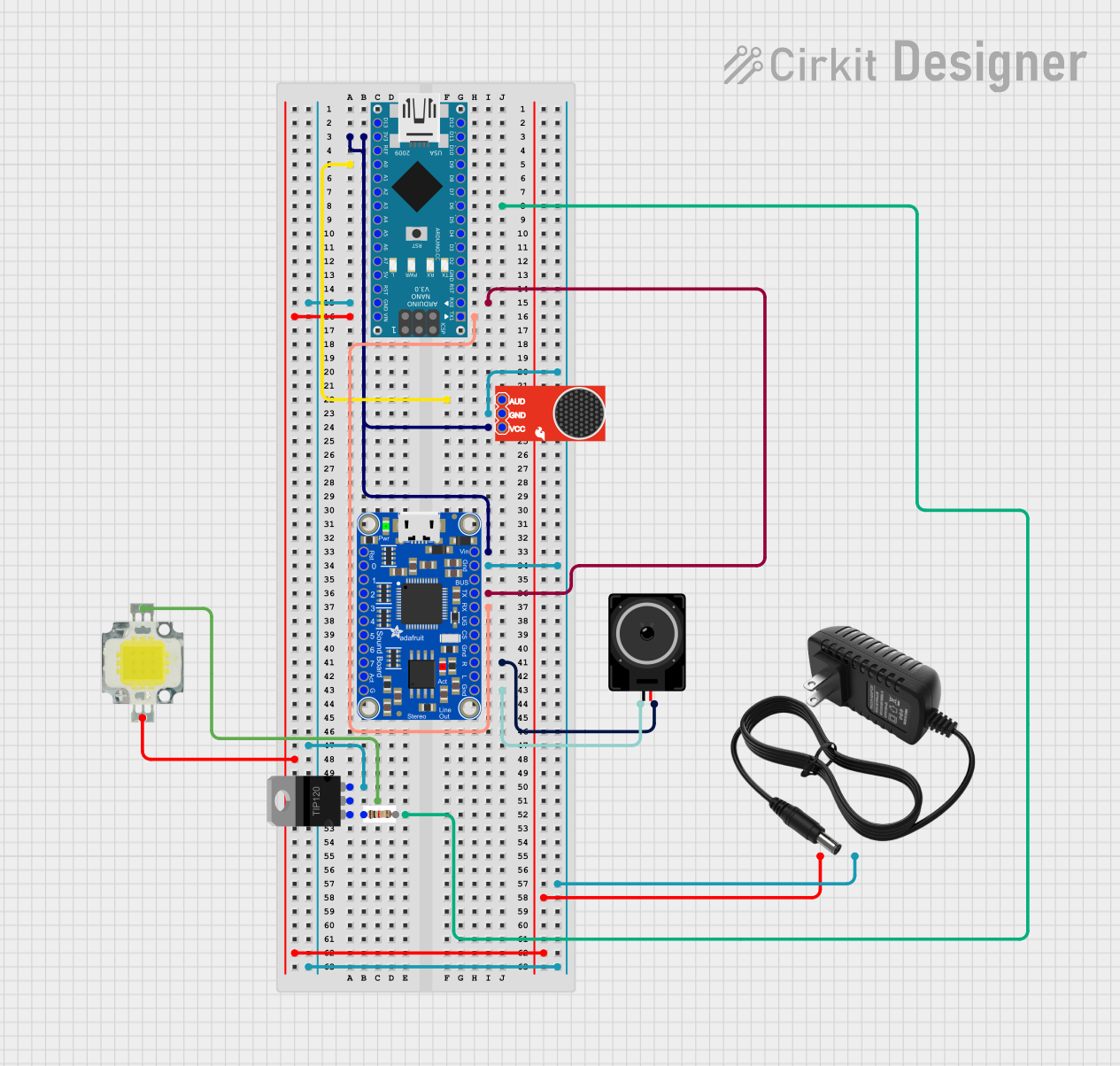
This circuit is designed to integrate an Arduino Nano with various components including an Adafruit Audio FX Mini Sound Board, a SparkFun Electret Microphone Breakout, a TIP120 Hi-Current Darlington Transistor, a 12V power supply, a loudspeaker, a Power LED, and a 1 kilohm resistor. The Arduino Nano serves as the central processing unit, controlling the LED and sound playback based on input from the microphone. The Adafruit Audio FX Mini Sound Board is used for audio output, which is played through the loudspeaker. The TIP120 transistor is used to control the high-current LED. The circuit is powered by a 12V power supply, which also powers the LED.
Component List
- Arduino Nano: A compact microcontroller board based on the ATmega328P, featuring digital and analog I/O pins.
- Adafruit Audio FX Mini Sound Board: A sound playback module capable of storing and playing WAV and OGG files.
- 12V Power Supply: Provides the necessary power to the circuit components.
- Loudspeaker: An electroacoustic transducer used to produce sound in response to an electrical audio signal input.
- TIP120 Hi-Current Darlington Transistor: A transistor used for controlling high-current loads.
- Power LED 12V 10W 0.8-0.9A: A high-power light-emitting diode for illumination.
- 1 kilohm Resistor: A resistor with a resistance of 1 kilohm, used for current limiting or voltage division.
- SparkFun Electret Microphone Breakout: A small and sensitive microphone with an onboard amplifier for audio signal capture.
Wiring Details
Arduino Nano
3V3connected to SparkFun Electret Microphone BreakoutVCCand Adafruit Audio FX Mini Sound BoardVINA0connected to SparkFun Electret Microphone BreakoutAUDD6connected to TIP120 TransistorBASE(via 1 kilohm resistor)GNDconnected to common ground netD0/RXconnected to Adafruit Audio FX Mini Sound BoardTXVINconnected to 12V power supply+and Power LED+D1/TXconnected to Adafruit Audio FX Mini Sound BoardRX_5V
Adafruit Audio FX Mini Sound Board
RST,GPIO0_0toGPIO0_7,ACT,L_AC,CS,UG,VBUSnot connectedVINconnected to Arduino Nano3V3GNDconnected to common ground netTXconnected to Arduino NanoD0/RXRX_5Vconnected to Arduino NanoD1/TXR_ACconnected to Loudspeakerpin2
12V Power Supply
+connected to Arduino NanoVINand Power LED+-connected to common ground net
Loudspeaker
pin1connected to Adafruit Audio FX Mini Sound BoardGNDpin2connected to Adafruit Audio FX Mini Sound BoardR_AC
TIP120 Hi-Current Darlington Transistor
BASEconnected to Arduino NanoD6(via 1 kilohm resistor)COLLECTORconnected to Power LED-EMITTERconnected to common ground net
Power LED 12V 10W 0.8-0.9A
+connected to 12V power supply+and Arduino NanoVIN-connected to TIP120 TransistorCOLLECTOR
1 kilohm Resistor
pin1connected to TIP120 TransistorBASEpin2connected to Arduino NanoD6
SparkFun Electret Microphone Breakout
VCCconnected to Arduino Nano3V3GNDconnected to common ground netAUDconnected to Arduino NanoA0
Documented Code
// Pin definitions
const int soundSensorPin = A0; // analog output connected to A0
const int ledPin = 6;          // LED bulb connected to D6
const int fxTriggerPin = 2;    // FX board trigger pin connected to D2

// Variables
bool ledState = false;         // To keep track of LED state
int clapCount = 0;             // To count the number of claps
unsigned long lastClapTime = 0; // To store the time of the last clap
int trackIndex = 0;            // To keep track of the current track for pin5

void setup() {
  pinMode(soundSensorPin, INPUT);
  pinMode(ledPin, OUTPUT);
  pinMode(fxTriggerPin, OUTPUT);
  Serial.begin(9600);          // Initialize serial communication for debugging
}

void loop() {
  int sensorValue = analogRead(soundSensorPin);

  // Detect clap (assuming a threshold value for clap detection)
  if (sensorValue > 600) { // Adjust threshold as needed
    delay(50); // Debounce delay
    if (analogRead(soundSensorPin) > 600) {
      unsigned long currentTime = millis();
      unsigned long timeBetweenClaps = (currentTime - lastClapTime) / 1000; // Convert to seconds
      lastClapTime = currentTime;

      clapCount++;
      Serial.println("Clap detected!");

      // Toggle LED state
      ledState = !ledState;
      digitalWrite(ledPin, ledState ? HIGH : LOW);

      // Determine which track to play based on time between claps and clap count
      if (timeBetweenClaps >= 30 && timeBetweenClaps <= 45) {
        if (clapCount % 2 == 1) {
          playRandomTrack(1); // Odd clap, play from pin1
        } else {
          playRandomTrack(2); // Even clap, play from pin2
        }
      } else if (timeBetweenClaps >= 15 && timeBetweenClaps < 30) {
        if (clapCount % 2 == 1) {
          playRandomTrack(3); // Odd clap, play from pin3
        } else {
          playRandomTrack(4); // Even clap, play from pin4
        }
      } else if (timeBetweenClaps < 15) {
        playSequentialTrack(5); // Play sequentially from pin5
      } else {
        // Default action if time between claps is outside specified ranges
        playRandomTrack(0); // Play a random track from GPIO0_0 to GPIO0_4
      }

      // Wait for a short period to avoid multiple detections of the same clap
      delay(500);
    }
  }
}

void playRandomTrack(int pin) {
  // Generate a random number between 0 and 3 (for 4 tracks)
  int trackNumber = random(0, 4);

  // Send the track number to the FX board
  // Assuming the FX board is set up to play tracks on GPIO0_0 to GPIO0_4
  digitalWrite(fxTriggerPin, LOW); // Reset the trigger pin
  delay(10);
  digitalWrite(fxTriggerPin, HIGH); // Trigger the pin
  delay(10);
  digitalWrite(fxTriggerPin, LOW); // Reset the trigger pin

  Serial.print("Playing track from pin");
  Serial.print(pin);
  Serial.print(": ");
  Serial.println(trackNumber);
}

void playSequentialTrack(int pin) {
  // Play the next track in order from pin5
  int trackNumber = trackIndex % 8; // There are 8 tracks
  trackIndex++;

  // Send the track number to the FX board
  digitalWrite(fxTriggerPin, LOW); // Reset the trigger pin
  delay(10);
  digitalWrite(fxTriggerPin, HIGH); // Trigger the pin
  delay(10);
  digitalWrite(fxTriggerPin, LOW); // Reset the trigger pin

  Serial.print("Playing sequential track from pin");
  Serial.print(pin);
  Serial.print(": ");
  Serial.println(trackNumber);
}
This code is designed to run on the Arduino Nano and controls the behavior of the circuit based on audio input from the microphone. It detects claps and toggles the state of the LED, as well as plays audio tracks from the Adafruit Audio FX Mini Sound Board. The code includes functions for playing random and sequential tracks based on the clap pattern detected.