
Arduino-Controlled Dual Motor System with IR and Water Level Sensing
View and Edit Project In Cirkit Designer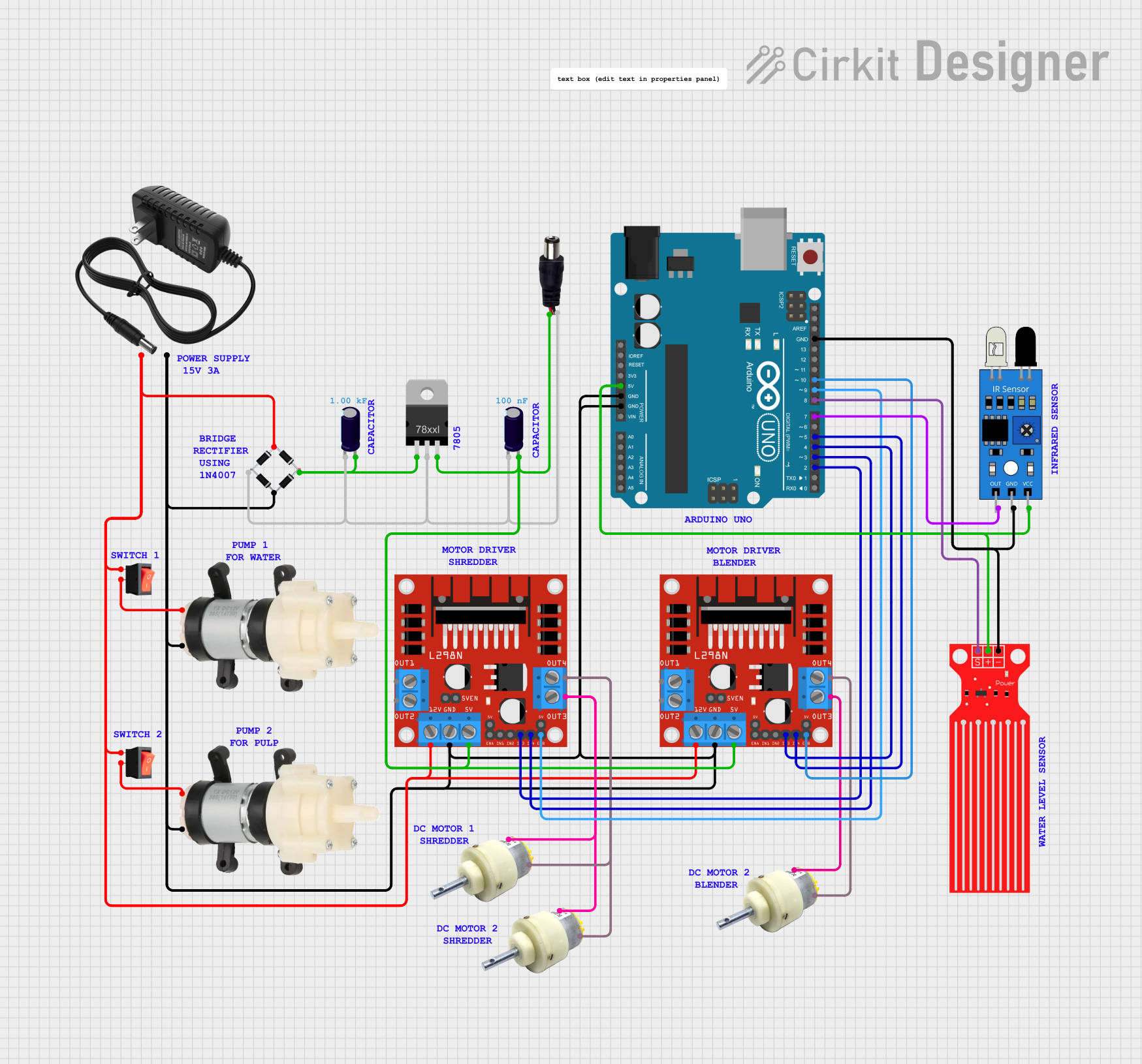
Circuit Documentation
Summary
This circuit is designed to control two DC gear motors and two mini diaphragm water pumps using an Arduino UNO microcontroller. The circuit includes a 12V power supply, bridge rectifier, voltage regulator, and electrolytic capacitors for power management. Two L298N DC motor drivers are used to control the motors and pumps. The circuit also features a water level sensor and an IR sensor for input, and rocker switches to control the power flow. The Arduino UNO is programmed to operate the motors and pumps based on the sensor inputs, with specific run times for each motor.
Component List
DC Gear Motor
- Description: A motor that converts electrical energy into mechanical energy with a gearbox for torque multiplication.
- Pins: Positive, Negative
Bridge Rectifier
- Description: A component that converts alternating current (AC) to direct current (DC).
- Pins: Source_in-, Source_out-, Source_out+, Source_in+
12V Power Supply
- Description: Provides a stable 12V DC power source for the circuit.
- Pins: +, -
Electrolytic Capacitor
- Description: A capacitor used for filtering and stabilizing the DC power supply.
- Pins: -, +
- Properties: Capacitance (various values)
Rocker Switch
- Description: A switch to control the connection and disconnection of the circuit.
- Pins: Output, Input
Voltage Regulator
- Description: Regulates the input voltage to a steady, lower output voltage.
- Pins: IN, GND, OUT
Arduino UNO
- Description: A microcontroller board based on the ATmega328P, used for controlling the logic of the circuit.
- Pins: Various digital and analog pins
IR Sensor
- Description: An infrared sensor used to detect objects in close proximity.
- Pins: Out, GND, VCC
L298N DC Motor Driver
- Description: A dual H-bridge motor driver that allows for speed and direction control of two DC motors.
- Pins: OUT1, OUT2, 12V, GND, 5V, OUT3, OUT4, ENA, IN1, IN2, IN3, IN4, ENB
Mini Diaphragm Water Pump
- Description: A pump used for moving water.
- Pins: Positive (+), Negative (-)
Water Level Sensor
- Description: A sensor used to detect the presence of water.
- Pins: SIG, VCC, GND
Power Jack
- Description: A connector used to supply power to the circuit.
- Pins: POSITIF, NEGATIF
Wiring Details
DC Gear Motor
- Positive connected to L298N DC motor driver OUT4
- Negative connected to L298N DC motor driver OUT3
Bridge Rectifier
- Source_in- connected to rocker switch input
- Source_out- connected to Electrolytic Capacitor -, Voltage Regulator GND, and power jack NEGATIF
- Source_out+ connected to Electrolytic Capacitor + and Voltage Regulator IN
- Source_in+ connected to Mini Diaphragm Water Pump Negative (-), L298N DC motor driver GND, Arduino UNO GND, and 12V power supply -
12V Power Supply
-
- connected to rocker switch input
-
- connected to Bridge rectifier source_in+
Electrolytic Capacitor
-
- connected to Bridge rectifier source_out-
-
- connected to Bridge rectifier source_out+
Rocker Switch
- Input connected to 12V power supply + and Bridge rectifier Source_in-
- Output connected to Mini Diaphragm Water Pump Positive (+)
Voltage Regulator
- IN connected to Bridge rectifier source_out+
- GND connected to Bridge rectifier source_out-
- OUT connected to L298N DC motor driver 5V, Electrolytic Capacitor +, and power jack POSITIF
Arduino UNO
- Various digital and analog pins connected to L298N DC motor driver control pins, IR sensor, and Water Level Sensor
IR Sensor
- Out connected to Arduino UNO D7
- GND connected to Arduino UNO GND
- VCC connected to Arduino UNO 5V
L298N DC Motor Driver
- OUT1/OUT2 connected to DC Gear Motor
- 12V connected to rocker switch input
- GND connected to Bridge rectifier source_in+
- 5V connected to Voltage Regulator OUT
- OUT3/OUT4 connected to DC Gear Motor
- ENA/IN1/IN2 connected to Arduino UNO for motor control
- ENB/IN3/IN4 connected to Arduino UNO for motor control
Mini Diaphragm Water Pump
- Positive (+) connected to rocker switch output
- Negative (-) connected to Bridge rectifier source_in+
Water Level Sensor
- SIG connected to Arduino UNO D8
- VCC connected to Arduino UNO 5V
- GND connected to Arduino UNO GND
Power Jack
- POSITIF connected to Voltage Regulator OUT
- NEGATIF connected to Bridge rectifier source_out-
Documented Code
// Pin definitions for motor control and sensors
const int motor1_IN1 = 2; // Motor 1 direction pin 1
const int motor1_IN2 = 3; // Motor 1 direction pin 2
const int motor1_ENA = 9; // Motor 1 speed control (ENA)
const int motor2_IN3 = 4; // Motor 2 direction pin 1 (IN3)
const int motor2_IN4 = 5; // Motor 2 direction pin 2 (IN4)
const int motor2_ENB = 10; // Motor 2 speed control (ENB)
const int irSensorPin = 7; // IR Sensor output pin
const int waterSensorPin = 8; // Water Sensor output pin

// Timing variables
unsigned long previousMillisMotor1 = 0; // Stores the last time motor 1 was started
const long motor1RunTime = 10000; // Motor 1 run time in milliseconds (10 seconds)
bool motor1Running = false; // Track if motor 1 is currently running

unsigned long previousMillisMotor2 = 0; // Stores the last time motor 2 was started
const long motor2RunTime = 30000; // Motor 2 run time in milliseconds (30 seconds)
bool motor2Running = false; // Track if motor 2 is currently running

void setup() {
  // Set motor control pins as outputs
  pinMode(motor1_IN1, OUTPUT);
  pinMode(motor1_IN2, OUTPUT);
  pinMode(motor1_ENA, OUTPUT);
  pinMode(motor2_IN3, OUTPUT);
  pinMode(motor2_IN4, OUTPUT);
  pinMode(motor2_ENB, OUTPUT);

  // Set the IR sensor pin and water sensor pin as inputs
  pinMode(irSensorPin, INPUT);
  pinMode(waterSensorPin, INPUT);

  // Start with motors stopped
  stopMotor1();
  stopMotor2();

  // Start Serial communication
  Serial.begin(9600); // Initialize Serial at 9600 baud rate
}

void loop() {
  // Read IR sensor value
  int irState = digitalRead(irSensorPin);
  // Read water sensor value
  int waterState = digitalRead(waterSensorPin);

  // Display the sensor readings on Serial Monitor
  Serial.print("IR Sensor State: ");
  Serial.print(irState); // Print the current state of the IR sensor
  Serial.print(" | Water Sensor State: ");
  Serial.println(waterState); // Print the current state of the water sensor

  // Run motor 1 if the IR sensor is triggered
  if (irState == LOW && !motor1Running) { // Object detected and motor 1 not already running
    startMotor1(); // Start motor 1 if object detected
    previousMillisMotor1 = millis(); // Record the start time for motor 1
    motor1Running = true; // Set motor1Running to true
  }

  // Stop motor 1 after 10 seconds
  if (motor1Running) {
    unsigned long currentMillis = millis();
    if (currentMillis - previousMillisMotor1 >= motor1RunTime) {
      stopMotor1(); // Stop motor 1 after 10 seconds
      motor1Running = false; // Reset motor1Running flag
    }
  }

  // Run motor 2 if the water sensor detects water and motor 2 is not already running
  if (waterState == HIGH && !motor2Running) {
    startMotor2(); // Start motor 2
    previousMillisMotor2 = millis(); // Record the start time for motor 2
    motor2Running = true; // Set motor2Running to true
  }

  // Stop motor 2 after 30 seconds
  if (motor2Running) {
    unsigned long currentMillis = millis();
    if (currentMillis - previousMillisMotor2 >= motor2RunTime) {
      stopMotor2(); // Stop motor 2 after 30 seconds
      motor2Running = false; // Reset motor2Running flag
    }
  }

  delay(100); // Add a small delay for readability
}

// Function to start Motor 1
void startMotor1() {
  digitalWrite(motor1_IN1, HIGH); // Set direction for Motor 1
  digitalWrite(motor1_IN