Cirkit Designer
Your all-in-one circuit design IDE
Home /
Project Documentation
Arduino-Controlled NRF24L01 Wireless DC Motor Driver System

Circuit Documentation
Summary
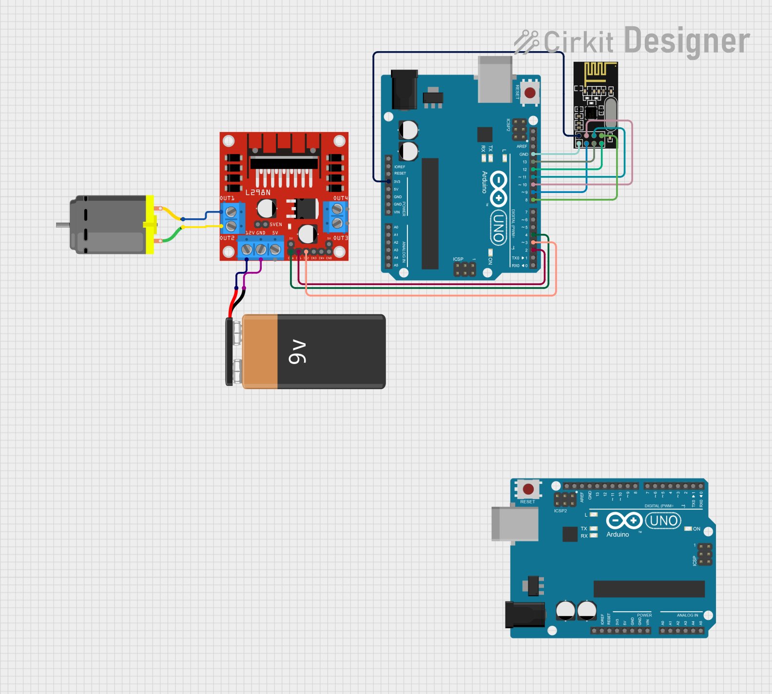
This circuit integrates an Arduino UNO microcontroller with an NRF24L01 wireless transceiver module, an L298N DC motor driver, a DC motor, and a 9V battery. The Arduino UNO is responsible for controlling the motor through the L298N driver and communicating wirelessly via the NRF24L01 module. The 9V battery provides power to the motor driver, which in turn controls the DC motor's operation.
Component List
Arduino UNO
- Microcontroller board based on the ATmega328P
- Features digital I/O pins, analog input pins, and various power pins
- Utilized for controlling peripherals and handling wireless communication
L298N DC Motor Driver
- Module for controlling up to two DC motors
- Provides H-bridge support for direction and speed control
- Powered by an external power source (9V battery in this case)
DC Motor
- Standard electric motor powered by DC voltage
- Controlled by the L298N motor driver for rotational movement
9V Battery
- Provides the power source for the motor driver and the DC motor
- Voltage supply for the L298N DC motor driver
NRF24L01
- 2.4GHz wireless transceiver module
- Enables wireless communication with other NRF24L01 equipped devices
- Connected to the Arduino UNO for SPI communication
Wiring Details
Arduino UNO
3.3Vconnected to NRF24L01VCC (3V)GNDconnected to NRF24L01GNDD13connected to NRF24L01SCKD12connected to NRF24L01MISOD11connected to NRF24L01MOSID10connected to NRF24L01CSND9connected to NRF24L01CED8connected to NRF24L01IRQ (not used)D4connected to L298NENAD3connected to L298NIN2D2connected to L298NIN1
L298N DC Motor Driver
OUT1connected to DC Motorpin 2OUT2connected to DC Motorpin 112Vconnected to 9V Battery+GNDconnected to 9V Battery-
DC Motor
pin 1connected to L298NOUT2pin 2connected to L298NOUT1
9V Battery
+connected to L298N12V-connected to L298NGND
NRF24L01
VCC (3V)connected to Arduino UNO3.3VGNDconnected to Arduino UNOGNDSCKconnected to Arduino UNOD13MISOconnected to Arduino UNOD12MOSIconnected to Arduino UNOD11CSNconnected to Arduino UNOD10CEconnected to Arduino UNOD9IRQ (not used)connected to Arduino UNOD8
Documented Code
Arduino UNO (Primary Controller)
void setup() {
  // put your setup code here, to run once:

}

void loop() {
  // put your main code here, to run repeatedly:

}
Filename: sketch.ino
Arduino UNO (Secondary Controller)
void setup() {
  // put your setup code here, to run once:

}

void loop() {
  // put your main code here, to run repeatedly:

}
Filename: sketch.ino
Note: The secondary Arduino UNO does not have any documented connections or specific code associated with it in the provided data. It is listed here for completeness, but further information is required to document its role in the circuit.