Arduino UNO-Based Smart Fan Controller with Temperature and Humidity Sensing
Circuit Documentation
Summary
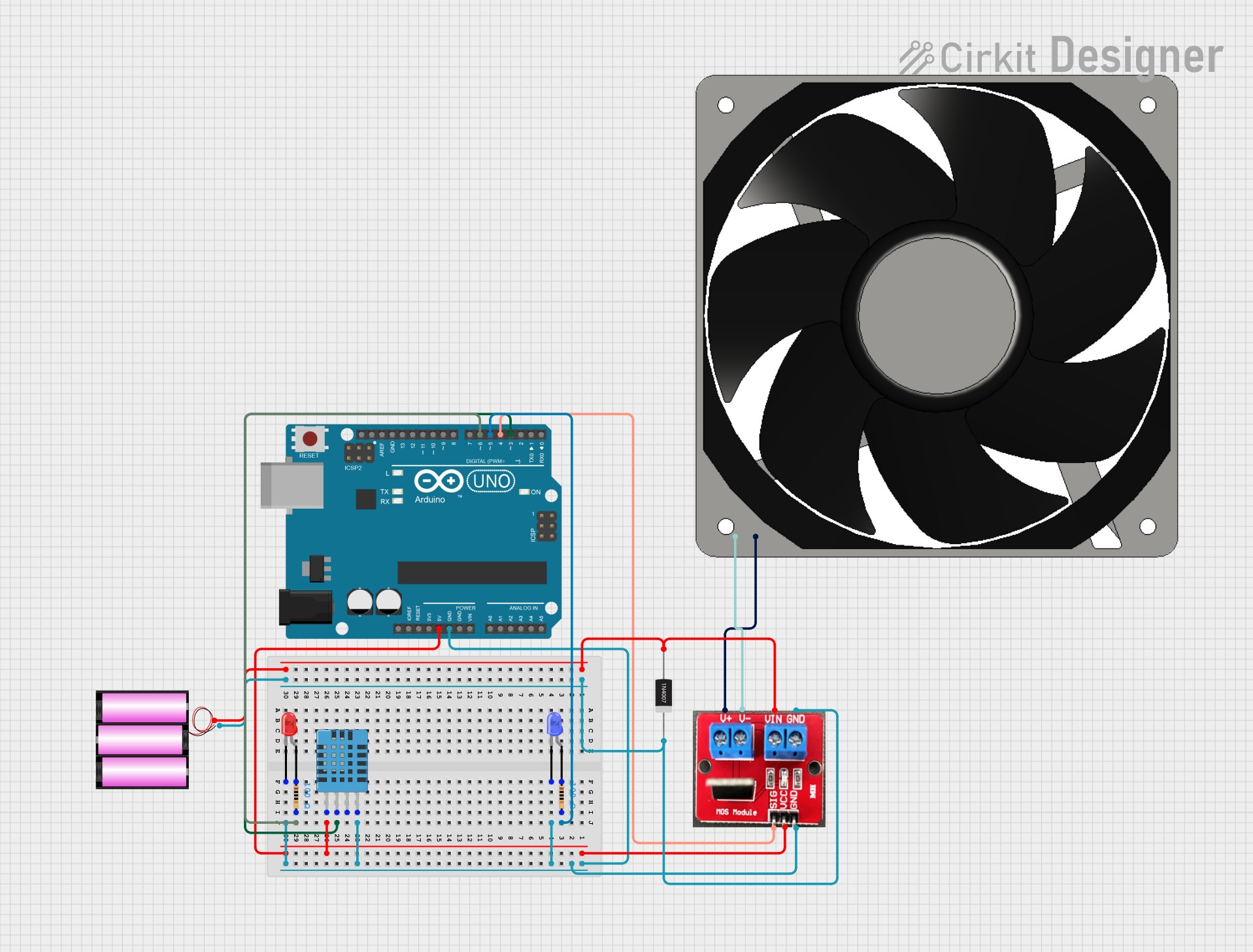
This circuit involves an Arduino UNO microcontroller, a 12V fan, a DHT11 humidity and temperature sensor, two LEDs (red and blue), resistors, a rectifier diode, and an IRF520 PWM module. The circuit is designed to control the fan and LEDs based on the sensor readings and other inputs.
Component List
Arduino UNO
- Description: A microcontroller board based on the ATmega328P.
- Pins: UNUSED, IOREF, Reset, 3.3V, 5V, GND, Vin, A0, A1, A2, A3, A4, A5, SCL, SDA, AREF, D13, D12, D11, D10, D9, D8, D7, D6, D5, D4, D3, D2, D1, D0
120 fan 12V
- Description: A 12V cooling fan.
- Pins: 12V+, GND
Resistor (100 Ohms)
- Description: A resistor with a resistance of 100 Ohms.
- Pins: pin1, pin2
LED: Two Pin (red)
- Description: A red LED.
- Pins: cathode, anode
LED: Two Pin (blue)
- Description: A blue LED.
- Pins: cathode, anode
1N4007 Rectifier Diode
- Description: A rectifier diode.
- Pins: Cathode, Anode
IRF520 PWM
- Description: A PWM module.
- Pins: V+, V-, Vin, GND, SIG, Vcc
DHT11 Humidity and Temperature Sensor
- Description: A sensor for measuring humidity and temperature.
- Pins: VDD, DATA, NULL, GND
Battery 12V
- Description: A 12V battery.
- Pins: +, -
Wiring Details
Arduino UNO
5V connected to:
- IRF520 PWM (Vcc)
- DHT11 Humidity and Temperature Sensor (VDD)
GND connected to:
- IRF520 PWM (GND)
- LED: Two Pin (blue) (cathode)
- DHT11 Humidity and Temperature Sensor (GND)
- LED: Two Pin (red) (cathode)
D6 connected to:
- Resistor (pin1)
- Resistor (pin2)
- LED: Two Pin (red) (anode)
D5 connected to:
- LED: Two Pin (blue) (anode)
- Resistor (pin1)
- Resistor (pin2)
D4 connected to:
- IRF520 PWM (SIG)
D3 connected to:
- DHT11 Humidity and Temperature Sensor (DATA)
120 fan 12V
12V+ connected to:
- IRF520 PWM (V+)
GND connected to:
- IRF520 PWM (V-)
Resistor (100 Ohms)
pin1 connected to:
- Resistor (pin2)
- LED: Two Pin (red) (anode)
- Arduino UNO (D6)
pin2 connected to:
- Resistor (pin1)
- LED: Two Pin (blue) (anode)
- Arduino UNO (D5)
LED: Two Pin (red)
cathode connected to:
- Arduino UNO (GND)
anode connected to:
- Resistor (pin1)
- Resistor (pin2)
- Arduino UNO (D6)
LED: Two Pin (blue)
cathode connected to:
- Arduino UNO (GND)
anode connected to:
- Resistor (pin1)
- Resistor (pin2)
- Arduino UNO (D5)
1N4007 Rectifier Diode
Anode connected to:
- IRF520 PWM (Vin)
- Battery 12V (+)
Cathode connected to:
- IRF520 PWM (GND)
- Battery 12V (-)
IRF520 PWM
Vcc connected to:
- Arduino UNO (5V)
GND connected to:
- Arduino UNO (GND)
- 1N4007 Rectifier Diode (Cathode)
- Battery 12V (-)
SIG connected to:
- Arduino UNO (D4)
V+ connected to:
- 120 fan 12V (12V+)
V- connected to:
- 120 fan 12V (GND)
Vin connected to:
- 1N4007 Rectifier Diode (Anode)
- Battery 12V (+)
DHT11 Humidity and Temperature Sensor
VDD connected to:
- Arduino UNO (5V)
DATA connected to:
- Arduino UNO (D3)
GND connected to:
- Arduino UNO (GND)
Battery 12V
+ connected to:
- 1N4007 Rectifier Diode (Anode)
- IRF520 PWM (Vin)
- connected to:
- 1N4007 Rectifier Diode (Cathode)
- IRF520 PWM (GND)
Documented Code
Arduino UNO Code (sketch.ino)
void setup() {
  // put your setup code here, to run once:

}

void loop() {
  // put your main code here, to run repeatedly:

}
Documentation (documentation.txt)