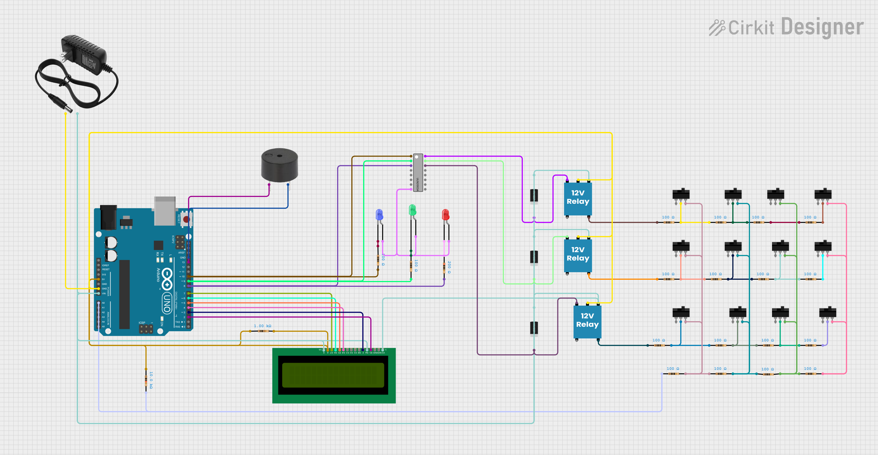
Arduino UNO Based Cable Fault Detection System with Relay Control and LCD Feedback

Circuit Documentation
Summary
The circuit in question appears to be a fault detection system that utilizes an Arduino UNO microcontroller to control a series of relays and gather sensor data. The system also includes visual indicators (LEDs) and an audible alert (buzzer). The Arduino UNO drives a 16x2 LCD display for user interface, indicating the status of three channels (presumably Red, Yellow, and Blue) and the distance to a fault if detected. The circuit includes multiple toggle switches, resistors, diodes, and relays to manage the flow of power and to protect against voltage spikes.
Component List
Microcontroller
- Arduino UNO: A microcontroller board based on the ATmega328P, with a variety of digital and analog I/O pins.
Indicators
- 16X2 LCD: A liquid crystal display capable of displaying 16 characters per line across 2 lines.
- LED: Two Pin (red)
- LED: Two Pin (blue)
- LED: Two Pin (green)
Actuators
- 12V Relay: An electrically operated switch that allows the control of a high voltage circuit by a low voltage signal.
- buzzer: An electronic buzzer for audible alerts.
Passive Components
- Resistors: Various resistors with different resistance values (100 Ohms, 200 Ohms, 1000 Ohms, 10000 Ohms).
- 1N4007 Rectifier Diode: A diode used for rectification, commonly used for reverse voltage protection.
Switches
- Toggle Switch: A switch that can connect or disconnect an electrical circuit.
Power Supply
- 12v power supply: Provides the necessary voltage for the circuit operation.
Driver IC
- ULN2003A: A 7-channel Darlington array used for driving high current loads.
Wiring Details
Arduino UNO
- Connected to the 5V and GND for power supply.
- Digital pins D2-D13 are used for interfacing with the LCD, relays, and buzzer.
- Analog pin A0 is used for reading sensor data.
16X2 LCD
- Powered by 5V and connected to GND.
- Data pins connected to Arduino digital pins D4-D7.
- Control pins RS and E connected to Arduino digital pins D2 and D3, respectively.
LEDs (Red, Blue, Green)
- Anodes connected to the ULN2003A outputs.
- Cathodes connected to their respective resistors, which are then connected to GND.
12V Relays
- Coil terminals connected to the ULN2003A outputs through diodes for flyback protection.
- Common (C) terminals connected to GND.
- Normally open (NO) terminals connected to resistors.
Buzzer
- One terminal connected to Arduino digital pin D13.
- Other terminal connected to GND.
Resistors
- Connected across various components for current limiting and pull-up/pull-down purposes.
Diodes
- Connected across the relay coils to prevent back EMF from damaging the circuit.
Toggle Switches
- Used to manually open or close the circuit paths.
ULN2003A
- Inputs connected to Arduino digital pins D8-D10.
- Outputs connected to relay coils and LED anodes.
- GND pin connected to GND.
Documented Code
#include <LiquidCrystal.h>
LiquidCrystal lcd(2,3,4,5,6,7);

#define sensor A0

#define relay1 8
#define relay2 9
#define relay3 10

#define buzzer 13

int read_ADC;
int distance;

byte symbol[8] = {
        B00000,
        B00100,
        B00100,
        B00100,
        B11111,
        B01110,
        B00100,
        B00000};

void setup() {
pinMode(sensor,INPUT);

pinMode(relay1, OUTPUT);
pinMode(relay2, OUTPUT);
pinMode(relay3, OUTPUT);

pinMode(buzzer, OUTPUT);

lcd.createChar(1, symbol);

lcd.begin(16, 2);
lcd.clear();
lcd.setCursor(0, 0); // set the cursor to column 0, line 2
lcd.print("Welcome to Cable");
lcd.setCursor(0, 1); // set the cursor to column 0, line 2
lcd.print("Fault  Detection");
delay(2000);
lcd.clear();
}

void loop(){
lcd.setCursor(1,0);
lcd.print("R");
lcd.write(1);

lcd.setCursor(7,0);
lcd.print("Y");
lcd.write(1);

lcd.setCursor(13,0);
lcd.print("B");
lcd.write(1);

digitalWrite(relay1,HIGH);
digitalWrite(relay2,LOW);
digitalWrite(relay3,LOW);
delay(500);

data();
lcd.setCursor(0,1);
if(distance>0){lcd.print(distance); lcd.print("KM  ");}
else{lcd.print(" NF ");}

digitalWrite(relay1,LOW);
digitalWrite(relay2,HIGH);
digitalWrite(relay3,LOW);
delay(500);

data();

lcd.setCursor(6,1);
if(distance>0){lcd.print(distance); lcd.print("KM  ");}
else{lcd.print(" NF ");}

digitalWrite(relay1,LOW);
digitalWrite(relay2,LOW);
digitalWrite(relay3,HIGH);
delay(500);

data();

lcd.setCursor(12,1);
if(distance>0){lcd.print(distance); lcd.print("KM  ");}
else{lcd.print(" NF ");}

}


void data(){
read_ADC = analogRead(sensor);
distance = read_ADC/100;

if(distance>9)distance = 0;

if(distance>0){
digitalWrite(buzzer,HIGH);
delay(200);
digitalWrite(buzzer,LOW);
delay(200);
 }
}
This code is designed to read sensor data and display the distance to a fault on an LCD. It controls three relays and a buzzer for alerts. The LCD displays "Welcome to Cable Fault Detection" on startup and then cycles through the relay states, displaying the distance or "NF" (no fault) accordingly.