
Arduino Mega 2560-Based Soil Nutrient Testing System with Bluetooth and LCD Display
View and Edit Project In Cirkit Designer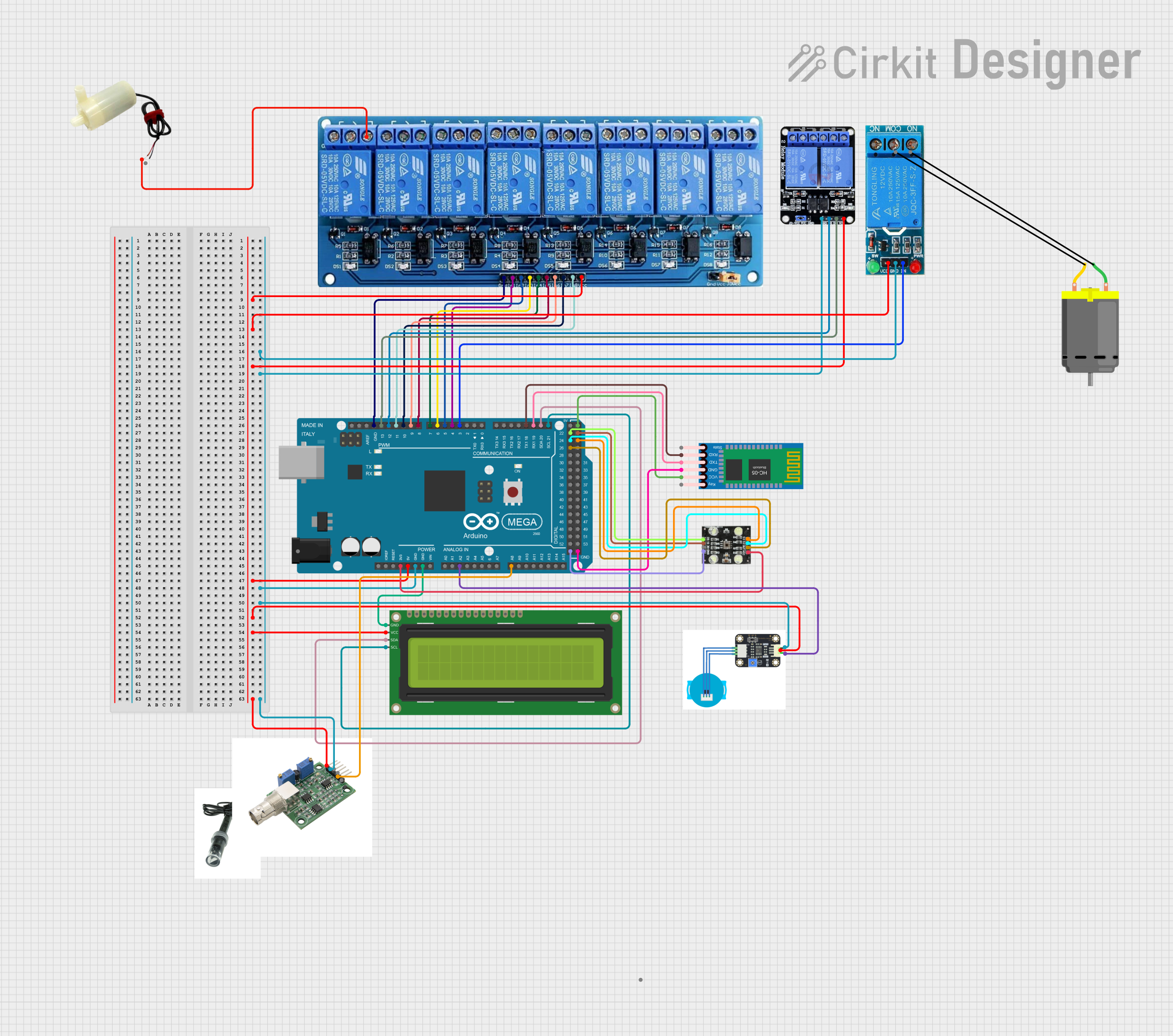
Circuit Documentation
Summary
This circuit is designed to perform various tests using sensors and relays controlled by an Arduino Mega 2560. The system includes a turbidity sensor, a color sensor, a Bluetooth module, multiple relays, an LCD display, and a water pump. The Arduino Mega 2560 serves as the central controller, interfacing with all the components to execute the tests and display results.
Component List
Arduino Mega 2560
- Description: Microcontroller board based on the ATmega2560.
- Pins: IOREF, RESET, 3V3, 5V, GND, VIN, A0-A15, D0-D53, AREF, SDA, SCL
Turbidity Sensor
- Description: Measures the turbidity (cloudiness) of water.
- Pins: gnd, in, vcc
TCS230 Color Sensor
- Description: Detects color by measuring the frequency of light.
- Pins: GND, OE, S1, S0, VCC, OUT, S2, S3
HC-05 Bluetooth Module
- Description: Enables wireless communication.
- Pins: Key, VCC, GND, TXD, RXD, State
5V 8-Channel Relay
- Description: Controls high voltage devices with a low voltage signal.
- Pins: GND, IN1-IN8, VCC, NC, C, NO
16x2 I2C LCD
- Description: Displays information in a 16x2 character format.
- Pins: GND, VCC, SDA, SCL
Two Channel Relay 5V
- Description: Controls two high voltage devices with a low voltage signal.
- Pins: VCC, IN2, IN1, GND, NC2, C2, NO2, NC1, C1, NO1
12V Single Channel Relay
- Description: Controls a single high voltage device with a low voltage signal.
- Pins: NC, COM, NO, IN, GND, VCC
DC Motor
- Description: Converts electrical energy into mechanical motion.
- Pins: pin 1, pin 2
5V Mini Water Pump
- Description: Pumps water when powered.
- Pins: positive pin, negative pin
Wiring Details
Arduino Mega 2560
- 5V: Connected to VCC of 5V 8-Channel Relay, 12V Single Channel Relay, Two Channel Relay 5V, Turbidity Sensor, 16x2 I2C LCD, and HC-05 Bluetooth Module.
- 3V3: Connected to VCC of TCS230 Color Sensor.
- GND: Connected to GND of 5V 8-Channel Relay, 12V Single Channel Relay, Two Channel Relay 5V, Turbidity Sensor, 16x2 I2C LCD, TCS230 Color Sensor, and HC-05 Bluetooth Module.
- A2: Connected to in of Turbidity Sensor.
- A8: Connected to D0 of phhhhh.
- D21/SCL: Connected to SCL of 16x2 I2C LCD.
- D20/SDA: Connected to SDA of 16x2 I2C LCD.
- D19/RX1: Connected to TXD of HC-05 Bluetooth Module.
- D18/TX1: Connected to RXD of HC-05 Bluetooth Module.
- D3 PWM: Connected to IN of 12V Single Channel Relay.
- D4 PWM: Connected to IN1 of 5V 8-Channel Relay.
- D5 PWM: Connected to IN2 of 5V 8-Channel Relay.
- D6 PWM: Connected to IN3 of 5V 8-Channel Relay.
- D7 PWM: Connected to IN4 of 5V 8-Channel Relay.
- D8 PWM: Connected to IN5 of 5V 8-Channel Relay.
- D9 PWM: Connected to IN6 of 5V 8-Channel Relay.
- D10 PWM: Connected to IN7 of 5V 8-Channel Relay.
- D11 PWM: Connected to IN8 of 5V 8-Channel Relay.
- D12 PWM: Connected to IN1 of Two Channel Relay 5V.
- D13 PWM: Connected to IN2 of Two Channel Relay 5V.
- D26: Connected to OUT of TCS230 Color Sensor.
- D24: Connected to S2 of TCS230 Color Sensor.
- D22: Connected to S0 of TCS230 Color Sensor.
- D25: Connected to S3 of TCS230 Color Sensor.
- D23: Connected to S1 of TCS230 Color Sensor.
Turbidity Sensor
- gnd: Connected to GND of Arduino Mega 2560.
- in: Connected to A2 of Arduino Mega 2560.
- vcc: Connected to 5V of Arduino Mega 2560.
TCS230 Color Sensor
- GND: Connected to GND of Arduino Mega 2560.
- VCC: Connected to 3V3 of Arduino Mega 2560.
- OUT: Connected to D26 of Arduino Mega 2560.
- S2: Connected to D24 of Arduino Mega 2560.
- S0: Connected to D22 of Arduino Mega 2560.
- S3: Connected to D25 of Arduino Mega 2560.
- S1: Connected to D23 of Arduino Mega 2560.
HC-05 Bluetooth Module
- GND: Connected to GND of Arduino Mega 2560.
- VCC: Connected to 5V of Arduino Mega 2560.
- TXD: Connected to D19/RX1 of Arduino Mega 2560.
- RXD: Connected to D18/TX1 of Arduino Mega 2560.
5V 8-Channel Relay
- GND: Connected to GND of Arduino Mega 2560.
- VCC: Connected to 5V of Arduino Mega 2560.
- IN1: Connected to D4 PWM of Arduino Mega 2560.
- IN2: Connected to D5 PWM of Arduino Mega 2560.
- IN3: Connected to D6 PWM of Arduino Mega 2560.
- IN4: Connected to D7 PWM of Arduino Mega 2560.
- IN5: Connected to D8 PWM of Arduino Mega 2560.
- IN6: Connected to D9 PWM of Arduino Mega 2560.
- IN7: Connected to D10 PWM of Arduino Mega 2560.
- IN8: Connected to D11 PWM of Arduino Mega 2560.
- NO: Connected to positive pin of 5V Mini Water Pump.
16x2 I2C LCD
- GND: Connected to GND of Arduino Mega 2560.
- VCC: Connected to 5V of Arduino Mega 2560.
- SDA: Connected to D20/SDA of Arduino Mega 2560.
- SCL: Connected to D21/SCL of Arduino Mega 2560.
Two Channel Relay 5V
- GND: Connected to GND of Arduino Mega 2560.
- VCC: Connected to 5V of Arduino Mega 2560.
- IN1: Connected to D12 PWM of Arduino Mega 2560.
- IN2: Connected to D13 PWM of Arduino Mega 2560.
12V Single Channel Relay
- GND: Connected to GND of Arduino Mega 2560.
- VCC: Connected to 5V of Arduino Mega 2560.
- IN: Connected to D3 PWM of Arduino Mega 2560.
5V Mini Water Pump
- positive pin: Connected to NO of 5V 8-Channel Relay.
Documented Code
#include "LiquidCrystal_I2C.h"
#include "Wire.h"

// Relay Pins
const int relayPins[] = {4, 5, 6, 7, 8, 9, 10, 11, 12, 13};
const int numRelays = sizeof(relayPins) / sizeof(relayPins[0]);

// LCD Setup
LiquidCrystal_I2C lcd(0x27, 16, 2);

// Turbidity Sensor
const int turbiditySensorPin = A2;

// Color Sensor
const int S0 = 22, S1 = 23, S2 = 24, S3 = 25, OUT = 26;

// Bluetooth
HardwareSerial &bt = Serial1;

// Variables
char option = "";

// Helper Function: Initialize Relays
void initializeRelays() {
  for (int i = 0; i < numRelays; i++) {
    pinMode(relayPins[i], OUTPUT);
    digitalWrite(relayPins[i], HIGH); // Default to OFF
  }
}

// Helper Function: Display Message on LCD
void display