
ESP32 Bluetooth-Controlled LED with Potentiometer and Pushbutton
View and Edit Project In Cirkit Designer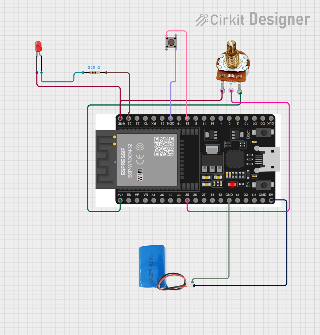
Circuit Documentation
Summary
This circuit is designed to control an LED using an ESP32 microcontroller via Bluetooth signals from an Android cell phone. The circuit includes a 5V battery for power, a rotary potentiometer for adjusting brightness, a pushbutton for manual control, and a resistor to limit current through the LED.
Component List
5V Battery
- Description: Provides power to the circuit.
- Pins: Positive, Negative
ESP32 38 PINS
- Description: Microcontroller used for controlling the LED and handling Bluetooth communication.
- Pins: GND, 23, 22/SCL, 1, 2, 21/SDA, 19, 18, 5, 17/TX2, 16/RX2, 4, 0, 15, D1, D0, CLK, 3V3, EN, VP, VN, 34, 35, 32, 33, 25, 26, 27, 14, 12, 13, D2, D3, 11, 5V/VIN
PR-Rotary Potentiometer
- Description: Used to adjust the brightness of the LED.
- Pins: GND, OUT, VCC
LED: Two Pin (red)
- Description: Indicates the status of the circuit.
- Pins: Cathode, Anode
Resistor
- Description: Limits the current through the LED.
- Pins: Pin1, Pin2
- Properties:
- Resistance: 200 Ohms
Pushbutton
- Description: Provides manual control for the LED.
- Pins: Pin 3 (out), Pin 4 (out), Pin 1 (in), Pin 2 (in)
Wiring Details
5V Battery
- Positive: Connected to ESP32 pin 5V/VIN
- Negative: Connected to ESP32 pin GND
ESP32 38 PINS
- 5V/VIN: Connected to 5V Battery Positive
- GND: Connected to 5V Battery Negative, PR-Rotary Potentiometer GND, LED Cathode, Pushbutton Pin 4 (out)
- 23: Connected to Resistor Pin2
- 18: Connected to Pushbutton Pin 1 (in)
- 3V3: Connected to PR-Rotary Potentiometer VCC
- 25: Connected to PR-Rotary Potentiometer OUT
PR-Rotary Potentiometer
- GND: Connected to ESP32 pin GND
- OUT: Connected to ESP32 pin 25
- VCC: Connected to ESP32 pin 3V3
LED: Two Pin (red)
- Cathode: Connected to ESP32 pin GND
- Anode: Connected to Resistor Pin1
Resistor
- Pin1: Connected to LED Anode
- Pin2: Connected to ESP32 pin 23
Pushbutton
- Pin 1 (in): Connected to ESP32 pin 18
- Pin 4 (out): Connected to ESP32 pin GND
Code Documentation
/*
 * This Arduino Sketch controls an LED connected to pin 23 of an ESP32
 * microcontroller via Bluetooth signals from an Android cell phone.
 * The LED can be turned on or off based on the received Bluetooth commands.
 */

#include <BluetoothSerial.h>

BluetoothSerial SerialBT;
const int ledPin = 23; // Pin connected to the LED

void setup() {
  pinMode(ledPin, OUTPUT); // Set the LED pin as an output
  SerialBT.begin("Svetlo_pico"); // Initialize Bluetooth with a name
  Serial.begin(9600); // Initialize serial communication at 9600 baud rate
  Serial.println("The device started, now you can pair it with Bluetooth!");
}

void loop() {
  // Waiting for command from mobile
  if (SerialBT.available()) {
    String command = SerialBT.readStringUntil('\n'); // Read command
    command.trim(); // Remove whitespace characters (e.g., \r or space)

    if (command.startsWith("SET ")) {
      int brightness = command.substring(4).toInt(); // Get value after "SET "
      brightness = constrain(brightness, 0, 255); // Limit value to range 0–255
      analogWrite(ledPin, brightness);
      SerialBT.println("Brightness set to " + String(brightness));
    }

    if (command == "ON") {
      digitalWrite(ledPin, HIGH); // Turn on LED
      SerialBT.println("LED ON");
      Serial.println("LED ON");
    } else if (command == "OFF") {
      digitalWrite(ledPin, LOW); // Turn off LED
      SerialBT.println("LED OFF");
      Serial.println("LED OFF");
    } else {
      SerialBT.println("Unknown command. Use ON or OFF.");
      Serial.println("Unknown command.");
    }
  }
}
This code initializes the ESP32 microcontroller to control an LED via Bluetooth. The LED can be turned on or off based on commands received from a paired Android cell phone. The code also allows for setting the brightness of the LED using a "SET" command followed by a value between 0 and 255.