
ESP32-Based Wi-Fi Controlled LED Indicator with Logic Level Conversion
View and Edit Project In Cirkit Designer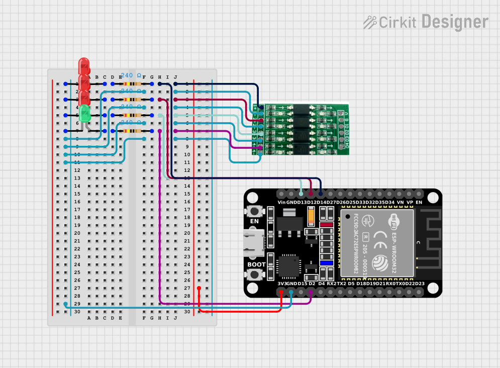
Circuit Documentation
Summary
This circuit involves an ESP32 microcontroller interfaced with a logic level converter, multiple resistors, and LEDs. The ESP32 controls the LEDs through the logic level converter, with resistors used to limit the current through the LEDs. The circuit is designed to demonstrate basic control of LEDs using an ESP32 microcontroller.
Component List
Logic Level Converter
- Pins: 1+, 1-, 2+, 2-, 3+, 3-, 4+, 4-, vcc, gnd, 01, 02, 03, 04
- Description: Converts voltage levels between different parts of the circuit.
Resistor (240 Ohms)
- Pins: pin1, pin2
- Description: Limits the current through the LEDs.
- Properties: Resistance = 240 Ohms
LED: Two Pin (red)
- Pins: cathode, anode
- Description: Emits red light when current flows through it.
LED: Two Pin (green)
- Pins: cathode, anode
- Description: Emits green light when current flows through it.
ESP32 (30 pin)
- Pins: EN, VP, VN, D34, D35, D32, D33, D25, D26, D27, D14, D12, D13, GND, Vin, D23, D22, TX0, RX0, D21, D19, D18, D5, TX2, RX2, D4, D2, D15, 3V3
- Description: A microcontroller used to control the LEDs.
Wiring Details
Logic Level Converter
1+ is connected to:
- Resistor pin2
- ESP32 D14
1- is connected to:
- LED (red) cathode
- LED (red) cathode
- LED (red) cathode
- LED (green) cathode
- Logic Level Converter 2-
- Logic Level Converter 3-
- Logic Level Converter 4-
- ESP32 GND
2+ is connected to:
- Resistor pin2
- ESP32 D12
2- is connected to:
- Logic Level Converter 1-
3+ is connected to:
- Resistor pin2
- ESP32 D13
3- is connected to:
- Logic Level Converter 1-
4+ is connected to:
- Resistor pin2
- ESP32 D2
4- is connected to:
- Logic Level Converter 1-
vcc is connected to:
- ESP32 3V3
gnd is connected to:
- ESP32 GND
Resistor (240 Ohms)
Resistor 1
- pin1 is connected to:
- LED (red) anode
- pin2 is connected to:
- Logic Level Converter 1+
- ESP32 D14
- pin1 is connected to:
Resistor 2
- pin1 is connected to:
- LED (red) anode
- pin2 is connected to:
- Logic Level Converter 2+
- ESP32 D12
- pin1 is connected to:
Resistor 3
- pin1 is connected to:
- LED (red) anode
- pin2 is connected to:
- Logic Level Converter 3+
- ESP32 D13
- pin1 is connected to:
Resistor 4
- pin1 is connected to:
- LED (green) anode
- pin2 is connected to:
- Logic Level Converter 4+
- ESP32 D2
- pin1 is connected to:
LED: Two Pin (red)
LED 1
- cathode is connected to:
- Logic Level Converter 1-
- anode is connected to:
- Resistor pin1
- cathode is connected to:
LED 2
- cathode is connected to:
- Logic Level Converter 1-
- anode is connected to:
- Resistor pin1
- cathode is connected to:
LED 3
- cathode is connected to:
- Logic Level Converter 1-
- anode is connected to:
- Resistor pin1
- cathode is connected to:
LED: Two Pin (green)
- LED 1
- cathode is connected to:
- Logic Level Converter 1-
- anode is connected to:
- Resistor pin1
- cathode is connected to:
ESP32 (30 pin)
D14 is connected to:
- Resistor pin2
- Logic Level Converter 1+
D12 is connected to:
- Resistor pin2
- Logic Level Converter 2+
D13 is connected to:
- Resistor pin2
- Logic Level Converter 3+
D2 is connected to:
- Resistor pin2
- Logic Level Converter 4+
GND is connected to:
- Logic Level Converter 1-
- Logic Level Converter gnd
3V3 is connected to:
- Logic Level Converter vcc
Code
No code is provided for this circuit.