
Arduino UNO Based Line Following Robot with IR Sensors and Motor Driver
View and Edit Project In Cirkit Designer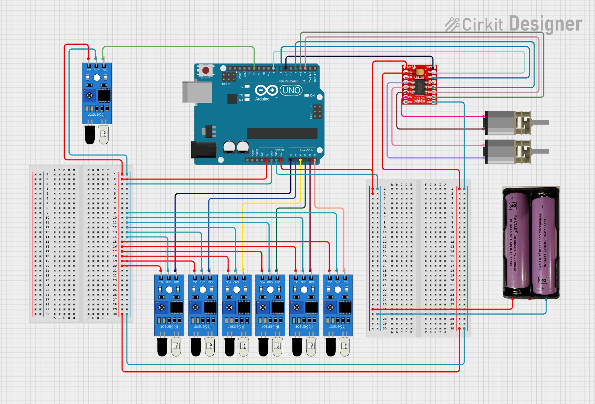
Circuit Documentation
Summary
This circuit is designed to control a pair of DC Mini Metal Gear Motors using an Arduino UNO microcontroller and a TB6612FNG Motor Driver. The circuit also includes multiple IR sensors that provide input to the Arduino for processing and decision-making. The Arduino is powered by a 7.4V power source, which also supplies power to the motor driver. The IR sensors are powered by the 5V output from the Arduino. The motors are controlled by PWM signals from the Arduino, which are fed to the motor driver to control the speed and direction of the motors.
Component List
Arduino UNO
- Microcontroller board based on the ATmega328P
- Provides I/O pins for interfacing with sensors and motor driver
- Can be powered via USB or external power source
IR Sensors
- Used to detect obstacles or lines for navigation
- Each sensor has an output, ground, and VCC pin
TB6612FNG Motor Driver
- Dual motor driver capable of driving two DC motors
- Has inputs for motor control signals and power supply
7.4V Power Source
- Provides power to the Arduino and motor driver
- Has positive (+) and negative (-) terminals
DC Mini Metal Gear Motors
- Two motors that provide movement to the system
- Each motor has two input pins for control signals
Wiring Details
Arduino UNO
- 5V pin connected to VCC of all IR sensors and VCC of the motor driver
- GND pin connected to GND of all IR sensors, GND of the motor driver, and positive (+) terminal of the 7.4V power source
- Vin pin connected to VM of the motor driver and negative (-) terminal of the 7.4V power source
- A0-A5 pins connected to the output of individual IR sensors
- D12 pin connected to the output of one IR sensor
- D2-D8 pins connected to control inputs of the motor driver
IR Sensors
- VCC pin connected to 5V of the Arduino
- GND pin connected to GND of the Arduino
- OUT pin connected to an analog input pin on the Arduino (A0-A5, D12)
TB6612FNG Motor Driver
- VCC pin connected to 5V of the Arduino
- GND pin connected to GND of the Arduino
- VM pin connected to Vin of the Arduino
- Motor control pins (AI1, AI2, BI1, BI2, PWMA, PWMB) connected to digital pins on the Arduino (D2-D8)
- Motor output pins (A01, A02, B01, B02) connected to the input pins of the DC Mini Metal Gear Motors
DC Mini Metal Gear Motors
- IN1 and IN2 pins of each motor connected to the corresponding motor output pins on the motor driver (A01, A02, B01, B02)
Documented Code
const int m11 = 4;
const int m12 = 2;
const int m21= 7;
const int m22 = 8;
const int m1pwm = 6; // PWM pin for left motor
const int m2pwm = 3; // PWM pin for right motor

float kP = 250;
int Speed = 160;
int kD = 0.0;
int last_val;

void setup() {
    Serial.begin(9600);
    pinMode(m11, OUTPUT);
    pinMode(m12, OUTPUT);
    pinMode(m21, OUTPUT);
    pinMode(m22, OUTPUT);
    pinMode(m1pwm, OUTPUT);
    pinMode(m2pwm, OUTPUT);
}

void loop() {
    int a0 = (analogRead(0) < 500 ? 0 : 1);
    int a1 = (analogRead(1) < 500 ? 0 : 1);
    int a2 = (analogRead(2) < 500 ? 0 : 1);
    int a3 = (analogRead(3) < 500 ? 0 : 1);
    int a4 = (analogRead(4) < 500 ? 0 : 1);
    int a5 = (analogRead(5) < 500 ? 0 : 1);

    int s_mode = digitalRead(12);

    int error = (a0 * 4.5) + (a1 * 3.5) + (a2 * 2.5) - (a3 * 2.5) - (a4 * 3.5) - (a5 * 4.5);

    int prop = map(error,-5.0,5.0,-kP,kP);

    int correction = prop + (error-last_val)*kD ;
    last_val = error;

    int leftMotorSpeed = constrain(Speed - correction, 0, 255);
    int rightMotorSpeed = constrain(Speed + correction, 0, 255);

    analogWrite(m1pwm, leftMotorSpeed);
    analogWrite(m2pwm, rightMotorSpeed);

    if (s_mode==0){
       Speed = 155;
    }else{
      Speed = 200;
      }

    digitalWrite(m11, LOW);
    digitalWrite(m12, HIGH);
    digitalWrite(m21, LOW);
    digitalWrite(m22, HIGH);
}
This code is responsible for reading the IR sensor values and adjusting the speed of the motors accordingly. The analogRead function is used to read the sensor values, which are then processed to calculate an error value. This error is used to adjust the motor speeds to keep the system on track. The digitalRead function checks the state of pin D12 to switch between two speed modes. The analogWrite function is used to control the speed of the motors through PWM signals.