
Arduino Nano-Based Wireless Input Controller with Joysticks and Sensors
View and Edit Project In Cirkit Designer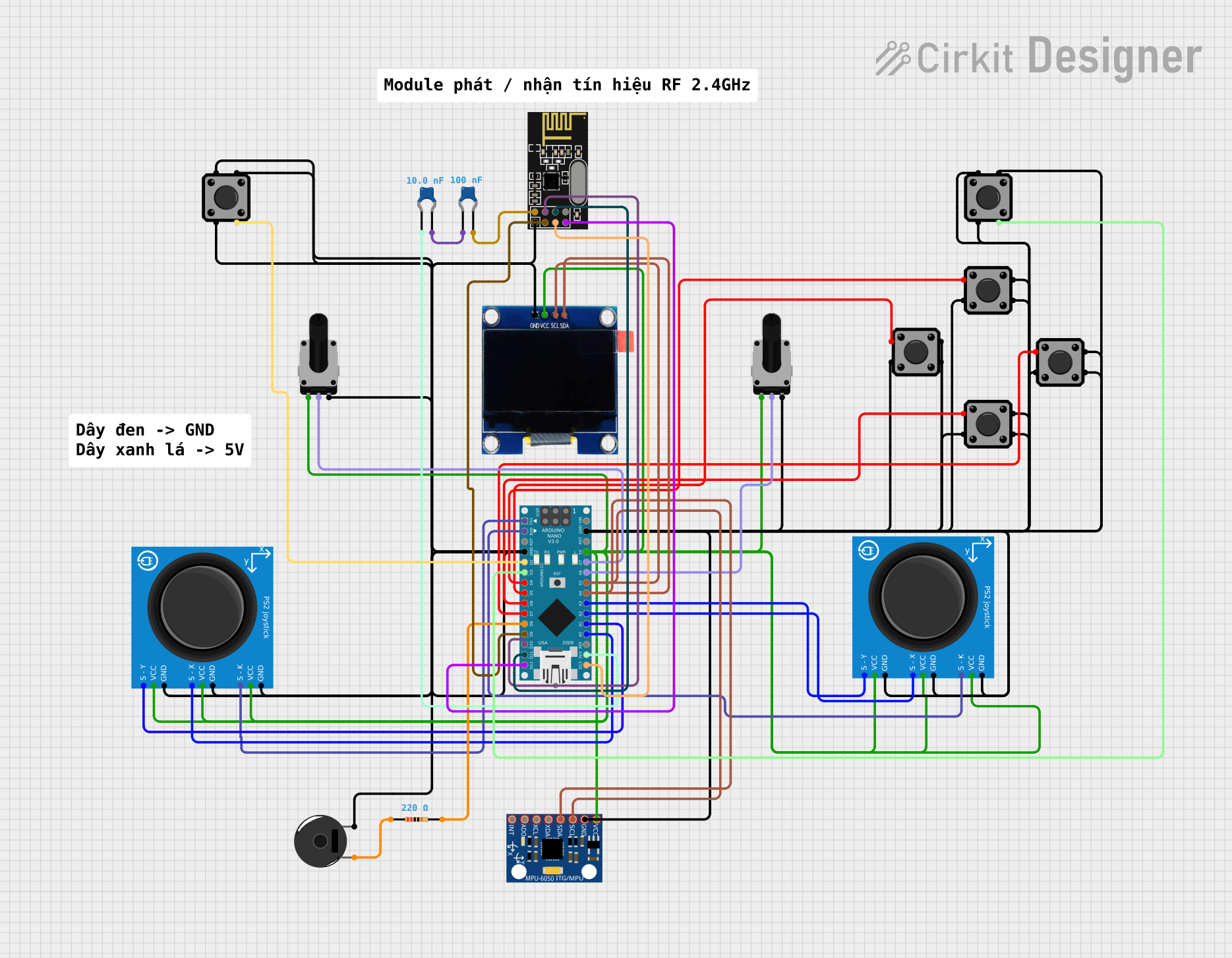
Circuit Documentation
Summary
This document provides a detailed overview of a circuit that includes an Arduino Nano as the central microcontroller, interfaced with various sensors, input devices, and communication modules. The circuit is designed to capture input from PS2 joysticks, tactile switch buttons, and potentiometers, display data on an OLED screen, communicate via an NRF24L01 module, and provide audio feedback through a piezo buzzer. The MPU-6050 sensor is included for motion tracking. The circuit is powered through the Arduino Nano's 5V output, and ground connections are distributed across the components.
Component List
Microcontroller
- Arduino Nano: A compact microcontroller board based on the ATmega328P, featuring digital and analog I/O pins.
Sensors and Input Devices
- PS2 Joystick: An analog joystick module with X and Y axis control and a pushbutton switch (S - K).
- Tactile Switch Buttons - 12mm Square: Simple pushbutton switches for user input.
- Rotary Potentiometer: A variable resistor with a knob used to provide analog input.
- MPU-6050: A motion processing unit that combines a 3-axis gyroscope and a 3-axis accelerometer.
Communication Module
- NRF24L01: A 2.4GHz wireless transceiver module for communication between devices.
Output Devices
- OLED 1.3": A small display screen for visual output.
- Piezo Buzzer: An electronic device that produces sound when voltage is applied.
Passive Components
- Resistor: A component used to resist the flow of electric current.
- Ceramic Capacitor: A passive component used to store energy in an electric field.
Wiring Details
Arduino Nano
- Digital pins D0-D13 are used for interfacing with tactile switches, PS2 joysticks, the NRF24L01 module, and the piezo buzzer.
- Analog pins A0-A7 are used for reading the potentiometers and PS2 joystick positions.
- The 5V and GND pins provide power and ground to other components.
- The 3V3 pin is connected to a ceramic capacitor.
PS2 Joystick
- The VCC and GND pins are connected to the power supply and ground.
- The S - X and S - Y pins are connected to the Arduino Nano's analog input pins for X and Y axis readings.
- The S - K pin is connected to the Arduino Nano's digital input pins.
Tactile Switch Buttons - 12mm Square
- One side of the switch is connected to the Arduino Nano's digital input pins.
- The other side of the switch is connected to ground.
Rotary Potentiometer
- The leg1 pin is connected to the power supply.
- The wiper pin is connected to the Arduino Nano's analog input pins.
- The leg2 pin is connected to ground.
NRF24L01
- The VCC and GND pins are connected to the power supply and ground.
- The CE and CSN pins are connected to the Arduino Nano's digital pins.
- The MOSI, MISO, and SCK pins are connected to the corresponding SPI pins on the Arduino Nano.
OLED 1.3"
- The VCC and GND pins are connected to the power supply and ground.
- The SCL and SDA pins are connected to the Arduino Nano's corresponding I2C pins.
Piezo Buzzer
- One pin is connected to the Arduino Nano's digital pin through a resistor.
- The other pin is connected to ground.
Resistor
- Connected in series with the piezo buzzer and the Arduino Nano.
Ceramic Capacitor
- One capacitor is connected between the 3V3 pin of the Arduino Nano and ground.
- Another capacitor is connected to the VCC pin of the NRF24L01 module.
Documented Code
Arduino Nano Code (sketch.ino)
void setup() {
  // put your setup code here, to run once:

}

void loop() {
  // put your main code here, to run repeatedly:

}
Additional Notes (documentation.txt)
No additional code documentation was provided.