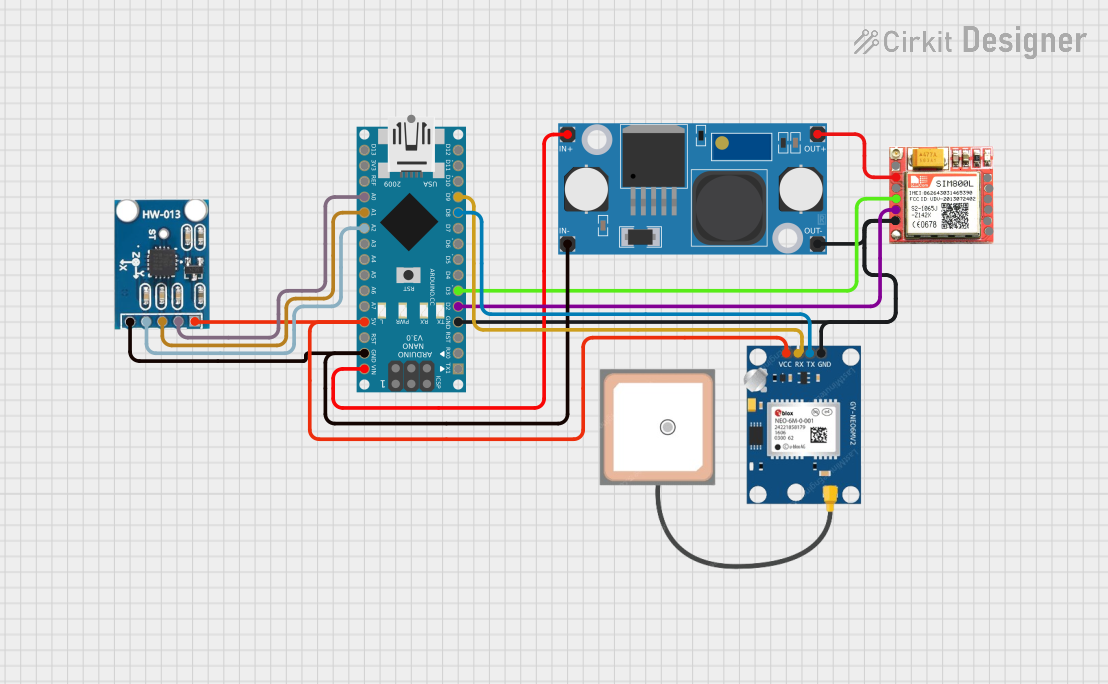
Arduino Nano Based GPS Tracker with GSM Communication and Accelerometer

Circuit Documentation
Summary
The circuit in question is composed of an Arduino Nano microcontroller interfaced with several peripheral modules: a SIM800L GSM module, a GPS NEO 6M module, an AITrip ADXL335 GY-61 accelerometer, and an LM2596 step-down voltage regulator module. The Arduino Nano serves as the central processing unit, managing communications, sensor data acquisition, and power distribution. The SIM800L module enables GSM communication capabilities, the GPS NEO 6M provides location services, and the ADXL335 accelerometer measures acceleration in three axes. The LM2596 module steps down the input voltage to a level suitable for powering the components.
Component List
Arduino Nano
- Microcontroller board based on the ATmega328P
- Offers a variety of digital and analog I/O pins
- Can be powered via USB or an external power supply
SIM800L GSM Module
- GSM/GPRS module for cellular communication
- Supports quad-band 850/900/1800/1900MHz
- Provides interfaces for a microphone and speaker
GPS NEO 6M Module
- GPS receiver module for satellite-based positioning
- Supports UART interface for communication with microcontrollers
AITrip ADXL335 GY-61 Accelerometer
- Analog accelerometer module for measuring acceleration in three axes (X, Y, Z)
- Outputs analog voltage proportional to acceleration
LM2596 Step Down Module
- Voltage regulator module that steps down input voltage to a lower output voltage
- Adjustable output for various applications
Wiring Details
Arduino Nano
- GND: Connected to the ground planes of SIM800L, GPS NEO 6M, ADXL335, and LM2596
- D2: Connected to TXD of SIM800L for serial communication
- D3: Connected to RXD of SIM800L for serial communication
- D8: Connected to TX of GPS NEO 6M for serial communication
- D9: Connected to RX of GPS NEO 6M for serial communication
- VIN: Connected to IN+ of LM2596 for power input
- 5V: Connected to VCC of ADXL335 and VCC of GPS NEO 6M for power distribution
- A0: Connected to X-Out of ADXL335 for analog acceleration data
- A1: Connected to Y-Out of ADXL335 for analog acceleration data
- A2: Connected to Z-Out of ADXL335 for analog acceleration data
SIM800L GSM Module
- GND: Connected to the ground plane
- TXD: Connected to D2 of Arduino Nano
- RXD: Connected to D3 of Arduino Nano
- VCC: Connected to OUT+ of LM2596 for power supply
GPS NEO 6M Module
- GND: Connected to the ground plane
- TX: Connected to D8 of Arduino Nano
- RX: Connected to D9 of Arduino Nano
- VCC: Connected to 5V of Arduino Nano
AITrip ADXL335 GY-61 Accelerometer
- GND: Connected to the ground plane
- Z-Out: Connected to A2 of Arduino Nano
- Y-Out: Connected to A1 of Arduino Nano
- X-Out: Connected to A0 of Arduino Nano
- VCC: Connected to 5V of Arduino Nano
LM2596 Step Down Module
- OUT-: Connected to the ground plane
- OUT+: Connected to VCC of SIM800L
- IN-: Connected to GND of Arduino Nano
- IN+: Connected to VIN of Arduino Nano
Documented Code
Arduino Nano Code (sketch.ino)
void setup() {
  // put your setup code here, to run once:

}

void loop() {
  // put your main code here, to run repeatedly:

}
Note: The provided code is a template and does not include specific functionality. It should be populated with the setup and loop routines required for the intended operation of the circuit.