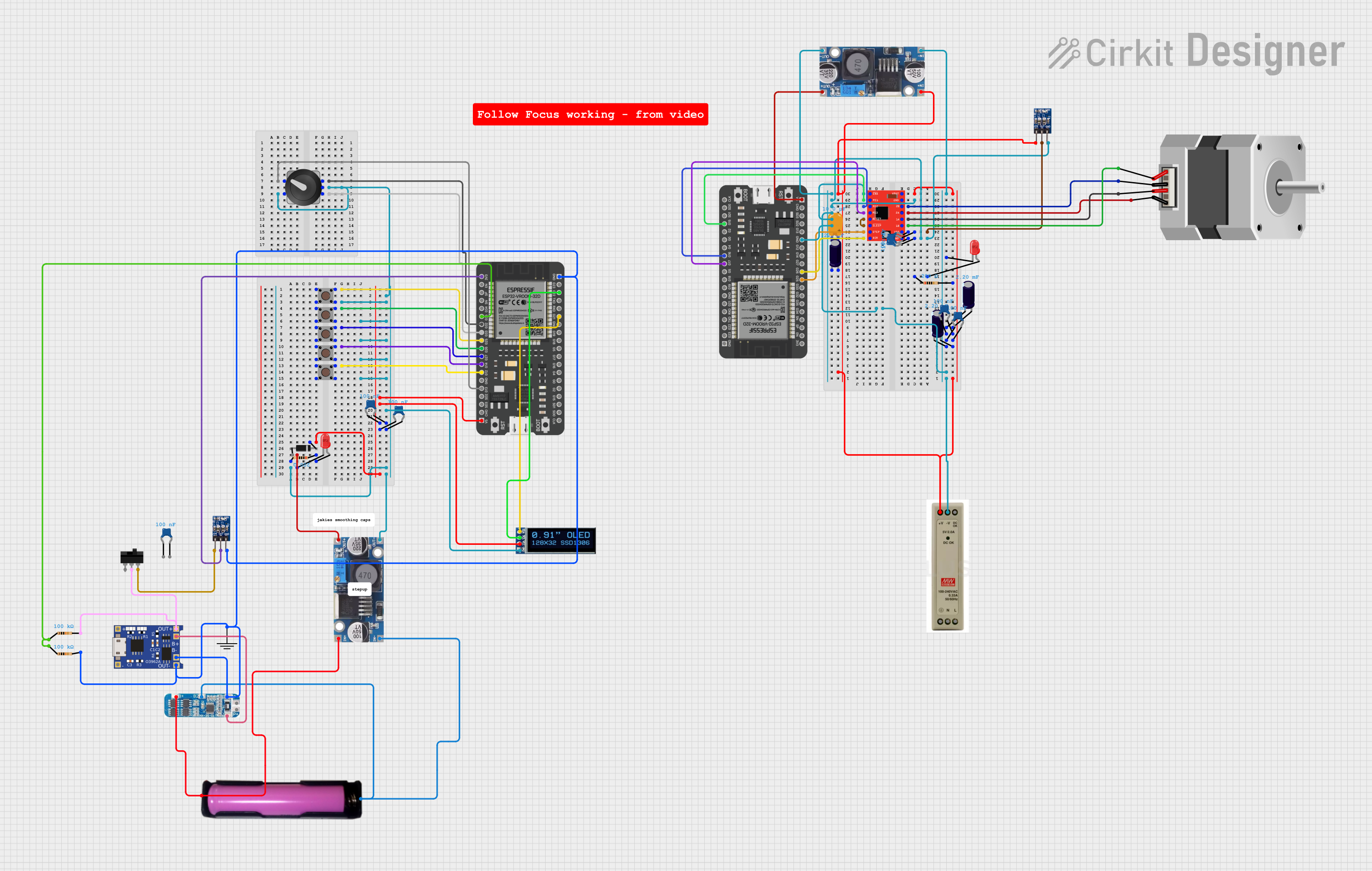
ESP32-Controlled A4988 Stepper Motor Driver Circuit

Circuit Documentation
Summary
This circuit appears to be designed to control a bipolar stepper motor using an A4988 stepper motor driver. The circuit includes power supply units, capacitors for filtering and decoupling, resistors for current limiting, diodes for power regulation, pushbuttons for user input, a rotary encoder for control, an OLED display for output, and two ESP32 microcontrollers for control logic. The circuit also includes a battery management system (BMS) with a TP4056 charging module and an 18650 battery holder for power management. The A4988 driver interfaces with the ESP32 microcontroller, which likely provides step and direction signals to control the motor's movements.
Component List
Active Components
- A4988 Stepper Motor Driver (Red): A module to drive a bipolar stepper motor.
- ESP32 - 38 pins: A microcontroller with Wi-Fi and Bluetooth capabilities.
- 5V PSU: A power supply unit that provides a regulated 5V output.
- ams1117 3.3: A voltage regulator that provides a 3.3V output.
- Step down Buck converter: A DC-DC converter that steps down voltage to a lower level.
- TP4056: A lithium battery charging module.
- BMS: A battery management system for lithium batteries.
- oled_display_128_32: An OLED display module for visual output.
Passive Components
- Ceramic Capacitor: Used for filtering and decoupling in the circuit.
- Electrolytic Capacitor: Used for filtering and providing bulk capacitance.
- Tantalum Capacitor: Another type of capacitor for filtering.
- LED (red): A light-emitting diode used as an indicator.
- Resistor: Used for current limiting and voltage division.
- Diode: Used for preventing reverse current flow.
- Pushbutton: A momentary switch for user input.
- Rotary Encoder with Knob: An input device for user control.
- Toggle Switch: A switch to control the flow of current in a circuit.
- Stepper Motor (Bipolar): A motor that converts digital pulses into mechanical rotation.
Power Components
- 18650 in holder: A battery holder for an 18650 lithium-ion cell.
Wiring Details
A4988 Stepper Motor Driver (Red)
- ENABLE, MS1, MS2, MS3: Connected to ESP32 for controlling stepping resolution.
- RESET, SLEEP: Tied together for normal operation.
- STEP, DIR: Connected to ESP32 for step and direction control.
- VMOT: Connected to 5V PSU through a resistor and capacitors for motor power.
- GND: Common ground with other components.
- 1A, 1B, 2A, 2B: Connected to the bipolar stepper motor.
- VDD: Connected to ams1117 3.3V output with ceramic capacitors for logic power.
ESP32 - 38 pins
- GND: Common ground with other components.
- 3V3: Connected to ams1117 3.3V output.
- G25, G26, G27, G14, G12: Connected to pushbuttons for user input.
- G13, G32, G33: Connected to rotary encoder for user input.
- G21, G22: Connected to OLED display for I2C communication.
- G15, G16, G17: Connected to A4988 for stepping resolution control.
Power Supply and Management
- 5V PSU: Provides 5V to the circuit.
- ams1117 3.3: Regulates voltage to 3.3V for ESP32 and other components.
- Step down Buck converter: Steps down voltage from the battery to a lower level.
- TP4056: Charges the 18650 battery.
- BMS: Manages the battery for safe charging and discharging.
- 18650 in holder: Provides power to the circuit.
Passive Components
- Ceramic Capacitors: Placed near power inputs of ICs for decoupling.
- Electrolytic Capacitors: Used for filtering on power lines.
- Tantalum Capacitor: Used for additional filtering.
- LEDs (red): Indicators connected through resistors.
- Resistors: Used for current limiting for LEDs and pull-up/down for inputs.
- Diode: Ensures correct power flow direction to the OLED display.
- Pushbuttons: User input devices connected to ESP32.
- Rotary Encoder with Knob: User input device connected to ESP32.
- Toggle Switch: Controls power input to the ams1117 3.3.
Indicators and User Interface
- LED (red): Indicates power or status, connected with a current-limiting resistor.
- OLED display: Shows information or status, connected to ESP32 via I2C.
Documented Code
No code was provided for the microcontrollers in the circuit. The expected code would handle the input from the pushbuttons and rotary encoder, control the A4988 stepper motor driver, and manage the display output on the OLED screen. It would also include routines for Wi-Fi or Bluetooth communication if those features of the ESP32 are utilized in the application.