
Circuit Documentation
Summary
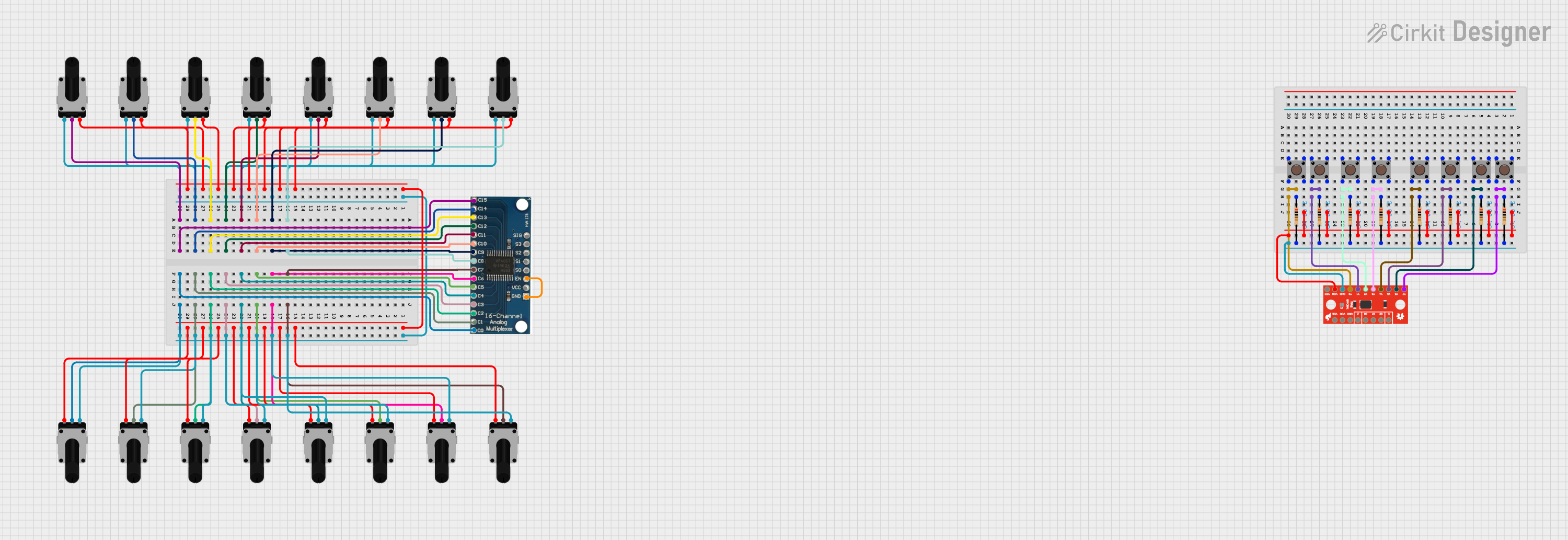
This circuit consists of a 16-channel analog multiplexer, multiple rotary potentiometers, pushbuttons, resistors, and an 8-channel multiplexer. The circuit is designed to read analog signals from the potentiometers and digital signals from the pushbuttons, which are then multiplexed for further processing.
Component List
16 Channel Analog Multiplexer Bob
- Pins: GND, VCC, EN, S0, S1, S2, S3, SIG, C0, C1, C2, C3, C4, C5, C6, C7, C8, C9, C10, C11, C12, C13, C14, C15
- Description: Analog multiplexer used to select one of the 16 input channels.
- Properties: None
Rotary Potentiometer
- Pins: leg1, wiper, leg2
- Description: Variable resistor used to adjust voltage levels.
- Properties: Resistance: 10,000 Ohms
SparkFun 74HC4051 8-Channel Mux Breakout
- Pins: Y7, Y6, Y5, Y4, Y3, Y2, Y1, Y0, GND, VCC, VEE, !E!, S2, S1, S0, Z
- Description: Digital multiplexer used to select one of the 8 input channels.
- Properties: None
Pushbutton
- Pins: Pin 3 (out), Pin 4 (out), Pin 1 (in), Pin 2 (in)
- Description: Momentary switch used to provide digital input.
- Properties: None
Resistor
- Pins: pin1, pin2
- Description: Fixed resistor used to limit current.
- Properties: Resistance: 2,000 Ohms
Wiring Details
16 Channel Analog Multiplexer Bob
- C0: Connected to the wiper of a Rotary Potentiometer
- C1: Connected to the wiper of a Rotary Potentiometer
- C2: Connected to the wiper of a Rotary Potentiometer
- C3: Connected to the wiper of a Rotary Potentiometer
- C4: Connected to the wiper of a Rotary Potentiometer
- C5: Connected to the wiper of a Rotary Potentiometer
- C6: Connected to the wiper of a Rotary Potentiometer
- C7: Connected to the wiper of a Rotary Potentiometer
- C8: Connected to the wiper of a Rotary Potentiometer
- C9: Connected to the wiper of a Rotary Potentiometer
- C10: Connected to the wiper of a Rotary Potentiometer
- C11: Connected to the wiper of a Rotary Potentiometer
- C12: Connected to the wiper of a Rotary Potentiometer
- C13: Connected to the wiper of a Rotary Potentiometer
- C14: Connected to the wiper of a Rotary Potentiometer
- C15: Connected to the wiper of a Rotary Potentiometer
- GND: Connected to EN pin of the same multiplexer
Rotary Potentiometer
- leg1: Connected to leg1 of all other Rotary Potentiometers
- leg2: Connected to leg2 of all other Rotary Potentiometers
- wiper: Connected to respective C pins of the 16 Channel Analog Multiplexer Bob
SparkFun 74HC4051 8-Channel Mux Breakout
- Y0: Connected to pin2 of a Resistor and Pin 2 (in) of a Pushbutton
- Y1: Connected to pin2 of a Resistor and Pin 2 (in) of a Pushbutton
- Y2: Connected to pin2 of a Resistor and Pin 2 (in) of a Pushbutton
- Y3: Connected to pin2 of a Resistor and Pin 2 (in) of a Pushbutton
- Y4: Connected to pin2 of a Resistor and Pin 2 (in) of a Pushbutton
- Y5: Connected to pin2 of a Resistor and Pin 2 (in) of a Pushbutton
- Y6: Connected to pin2 of a Resistor and Pin 2 (in) of a Pushbutton
- Y7: Connected to pin2 of a Resistor and Pin 2 (in) of a Pushbutton
- GND: Connected to pin2 of all Resistors
Pushbutton
- Pin 2 (in): Connected to pin1 of a Resistor and respective Y pins of the SparkFun 74HC4051 8-Channel Mux Breakout
- Pin 4 (out): Connected to Pin 4 (out) of all other Pushbuttons and VCC of the SparkFun 74HC4051 8-Channel Mux Breakout
Resistor
- pin1: Connected to Pin 2 (in) of a Pushbutton
- pin2: Connected to GND of the SparkFun 74HC4051 8-Channel Mux Breakout
Code
No code is provided for this circuit.
This documentation provides a comprehensive overview of the circuit, including a summary, detailed component list, wiring details, and code (if any).