
Circuit Documentation
Summary of the Circuit
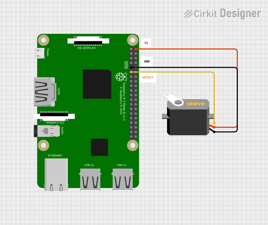
This circuit integrates a Raspberry Pi 3B with a servo motor. The Raspberry Pi 3B is used as the control unit, providing power and control signals to the servo. The servo motor is connected to the Raspberry Pi via its power, ground, and control (pulse) lines. The Raspberry Pi's GPIO17 pin is used to send pulse-width modulation (PWM) signals to control the position of the servo motor. The servo is powered directly from the Raspberry Pi's 5V pin.
Component List
Raspberry Pi 3B
- Description: A small single-board computer with a variety of digital GPIO pins.
- Pins: 3v3, GPIO2, GPIO3, GPIO4, GND, GPIO17, GPIO27, GPIO22, 3V3, GPIO10, GPIO9, GPIO11, ID_SD, GPIO5, GPIO6, GPIO13, GPIO19, GPIO26, GPIO21, GPIO20, GPIO16, GPIO12, ID_SC, GPIO7, GPIO8, GPIO25, GPIO24, GPIO23, GPIO18, GPIO15, GPIO14, 5V
- Purpose: Acts as the control unit for the servo motor, providing power and control signals.
Servo
- Description: An actuator that can be precisely controlled for angular or linear position, velocity, and acceleration.
- Pins: gnd, vcc, pulse
- Purpose: Receives control signals from the Raspberry Pi to adjust its position according to the PWM signal received on the pulse pin.
Comments
- Description: Placeholder components that may represent annotations or notes in the circuit design. These components do not have physical pins or electrical function in the circuit.
Wiring Details
Raspberry Pi 3B
- Ground (GND): Connects to the ground (gnd) pin of the Servo.
- GPIO17: Connects to the pulse pin of the Servo to provide control signals.
- 5V: Provides power to the vcc pin of the Servo.
Servo
- Ground (gnd): Connected to the GND pin of the Raspberry Pi 3B.
- VCC (vcc): Connected to the 5V pin of the Raspberry Pi 3B to receive power.
- Pulse (pulse): Connected to the GPIO17 pin of the Raspberry Pi 3B to receive control signals.
Documented Code
No code has been provided for the microcontrollers in the circuit. Typically, the Raspberry Pi 3B would run a Python script or another program to generate PWM signals on GPIO17 to control the servo motor. However, since no code is available, this section is left blank. If code becomes available, it should be documented here with explanations for setup, initialization, and the main control loop.