
Arduino Mega 2560 Autonomous Cleaning Robot with Ultrasonic Sensors and Bluetooth Control
View and Edit Project In Cirkit Designer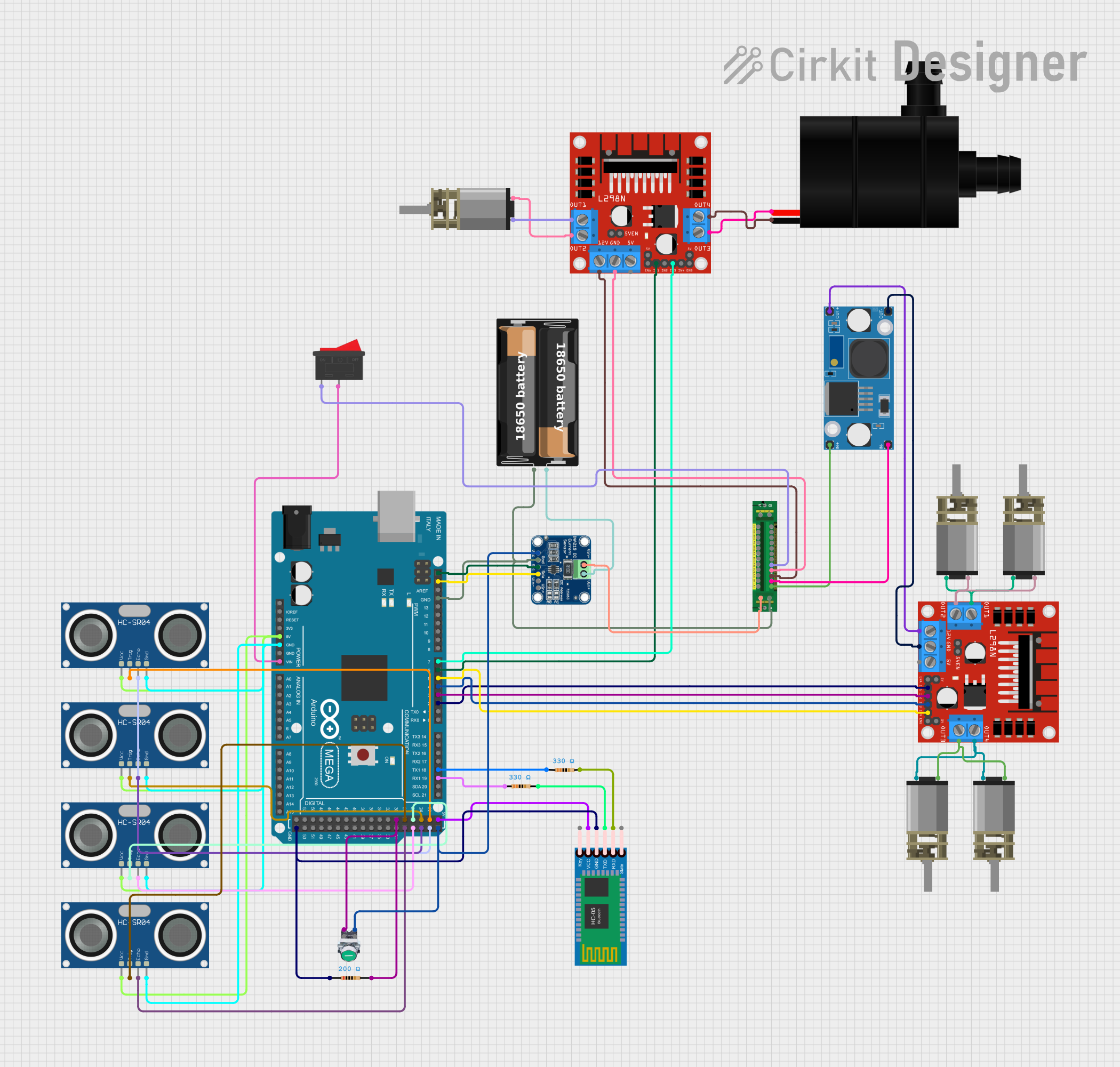
Circuit Documentation
Summary
This document provides a detailed overview of a circuit designed to control multiple DC motors, a water pump, and ultrasonic sensors using an Arduino Mega 2560. The circuit also includes a Bluetooth module for wireless communication and a power distribution board for managing power supply. The system is capable of both manual and autonomous operation modes.
Component List
DC Mini Metal Gear Motor
- Description: Small DC motor with metal gears.
- Pins: IN1, IN2
Rocker Switch
- Description: A simple on/off switch.
- Pins: 1, 2
HC-SR04 Ultrasonic Sensor
- Description: Ultrasonic distance sensor.
- Pins: VCC, TRIG, ECHO, GND
L298N DC Motor Driver
- Description: Dual H-Bridge motor driver.
- Pins: OUT1, OUT2, 12V, GND, 5V, OUT3, OUT4, 5V-ENA-JMP-I, 5V-ENA-JMP-O, +5V-J1, +5V-J2, ENA, IN1, IN2, IN3, IN4, ENB
Water Pump
- Description: Small water pump.
- Pins: +, -
My Battery Case
- Description: Battery holder.
- Pins: +, -
HC-05 Bluetooth Module
- Description: Bluetooth communication module.
- Pins: Key, VCC, GND, TXD, RXD, State
LM2596 Step Down Module
- Description: Voltage step-down converter.
- Pins: OUT-, OUT+, IN-, IN+
Resistor
- Description: Resistor with specified resistance.
- Pins: pin1, pin2
- Properties:
- Resistance: 330 Ohms
- Resistance: 200 Ohms
Pushbutton START
- Description: Pushbutton switch.
- Pins: NC, NO
INA219
- Description: Current and power monitor.
- Pins: VCC, GND, SCL, SDA, VIN -, VIN +
Power Distribution Board
- Description: Board for distributing power to multiple components.
- Pins: Output 1+, Input +, Input -, Output 2+, Output 2-, Output 3+, Output 4+, Output 5+, Output 1-, Output 4-, Output 3-, Output 5-, Output 6+, Output 6-, Output 7+, Output 7-, Output 8+, Output 8-, Output 9+, Output 9-, Output 10+, Output 10-, Output 11+, Output 11-, Output 12+, Output 12-, Output +, Output -
Arduino Mega 2560
- Description: Microcontroller board.
- Pins: IOREF, RESET, 3V3, 5V, GND, VIN, A0-A15, D21/SCL, D20/SDA, D19/RX1, D18/TX1, D17 PWM/RX2, D16 PWM/TX2, D15/RX3, D14/TX3, D0 RX0, D1 TX0, D2 PWM, D3 PWM, D4 PWM, D5 PWM, D6 PWM, D7 PWM, D8 PWM, D9 PWM, D10 PWM, D11 PWM, D12 PWM, D13 PWM, AREF, SDA, SCL, D52, D50, D48, D46, D44, D42, D40, D38, D36, D34, D32, D30, D28, D26, D24, D22, D53, D51, D49, D47, D45, D43, D41, D39, D37, D35, D33, D31, D29, D27, D25, D23
Wiring Details
DC Mini Metal Gear Motor
- IN1 connected to L298N DC motor driver OUT1
- IN2 connected to L298N DC motor driver OUT2
Rocker Switch
- Pin 1 connected to Power Distribution Board Output 3+
- Pin 2 connected to Arduino Mega 2560 VIN
HC-SR04 Ultrasonic Sensor
- VCC connected to Arduino Mega 2560 5V
- TRIG connected to Arduino Mega 2560 D28
- ECHO connected to Arduino Mega 2560 D29
- GND connected to Arduino Mega 2560 GND
L298N DC Motor Driver
- OUT1 connected to DC Mini Metal Gear Motor IN1
- OUT2 connected to DC Mini Metal Gear Motor IN2
- 12V connected to Power Distribution Board Output 2+
- GND connected to Power Distribution Board Output 2-
- IN1 connected to Arduino Mega 2560 D2 PWM
- IN2 connected to Arduino Mega 2560 D3 PWM
- IN3 connected to Arduino Mega 2560 D4 PWM
- IN4 connected to Arduino Mega 2560 D5 PWM
Water Pump
- + connected to L298N DC motor driver OUT3
- - connected to L298N DC motor driver OUT4
My Battery Case
- + connected to INA219 VIN +
- - connected to INA219 GND
HC-05 Bluetooth Module
- VCC connected to Arduino Mega 2560 5V
- GND connected to Arduino Mega 2560 GND
- TXD connected to Resistor pin2
- RXD connected to Resistor pin2
LM2596 Step Down Module
- OUT+ connected to L298N DC motor driver 12V
- OUT- connected to L298N DC motor driver GND
- IN- connected to Power Distribution Board Output 1-
- IN+ connected to Power Distribution Board Output 1+
Resistor
- pin1 connected to Arduino Mega 2560 D19/RX1
- pin2 connected to HC-05 Bluetooth Module TXD
Pushbutton START
- NO connected to Arduino Mega 2560 D30
INA219
- VIN + connected to My Battery Case +
- GND connected to Arduino Mega 2560 GND
- SDA connected to Arduino Mega 2560 SDA
- SCL connected to Arduino Mega 2560 SCL
Power Distribution Board
- Output 3+ connected to Rocker Switch Pin 1
- Output 2+ connected to L298N DC motor driver 12V
- Output 2- connected to L298N DC motor driver GND
- Output 1- connected to LM2596 Step Down Module IN-
- Output 1+ connected to LM2596 Step Down Module IN+
Arduino Mega 2560
- VIN connected to Rocker Switch Pin 2
- 5V connected to HC-SR04 Ultrasonic Sensor VCC
- GND connected to HC-SR04 Ultrasonic Sensor GND
- D2 PWM connected to L298N DC motor driver IN1
- D3 PWM connected to L298N DC motor driver IN2
- D4 PWM connected to L298N DC motor driver IN3
- D5 PWM connected to L298N DC motor driver IN4
- D6 PWM connected to L298N DC motor driver IN1 (second)
- D7 PWM connected to L298N DC motor driver IN3 (second)
- D28 connected to HC-SR04 Ultrasonic Sensor TRIG
- D29 connected to HC-SR04 Ultrasonic Sensor ECHO
- D30 connected to Pushbutton START NO
- D19/RX1 connected to Resistor pin1
- D18/TX1 connected to Resistor pin1
- SDA connected to INA219 SDA
- SCL connected to INA219 SCL
Code Documentation
#include <Wire.h>
#include <Adafruit_INA219.h>

// Pin definitions
const int motorR = 2;  // L298N IN1
const int motorL = 3;  // L298N IN2
const int motorF = 4;  // L298N IN3
const int motorB = 5;  // L298N IN4
const int brushMotor = 6;  // L298N IN1 (secondo L298N)
const int pumpMotor = 7;  // L298N IN3 (secondo L298N)
const int trigPinFront = 22;  // Front ultrasonic sensor trigger
const int echoPinFront = 23;  // Front ultrasonic sensor echo
const int trigPinBack = 24;  //