Cirkit Designer
Your all-in-one circuit design IDE
Home /
Project Documentation
Arduino UNO Controlled Servo Array with Flex Sensor Feedback
Circuit Documentation
Summary
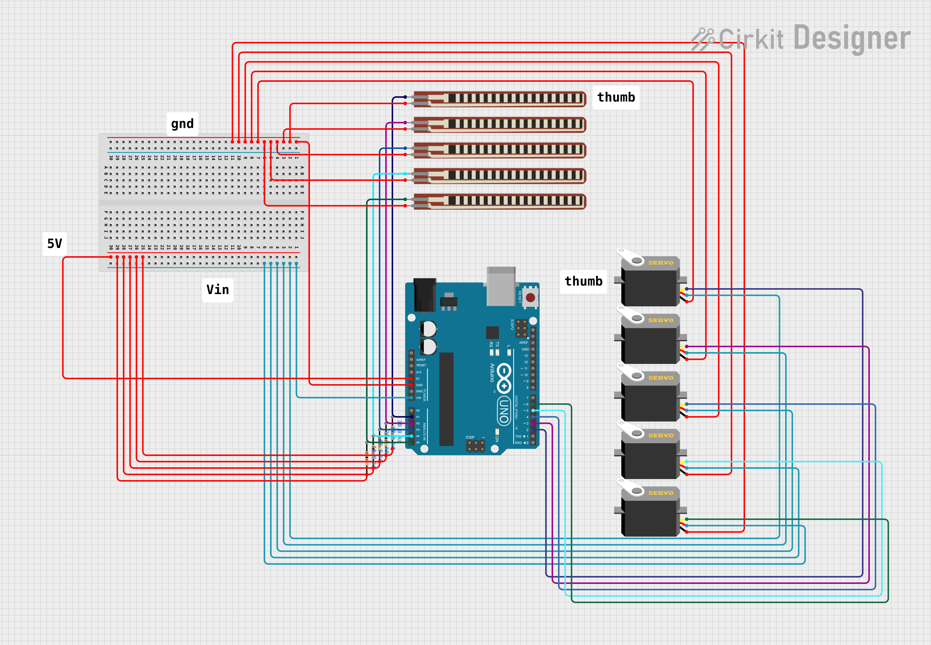
This circuit is designed around an Arduino UNO microcontroller and includes several peripherals: flex resistors to measure bending or flexing, servos for actuation, and fixed-value resistors for voltage/current control. The flex resistors are connected to the analog inputs of the Arduino to measure analog changes, while the servos are controlled via digital outputs. The fixed-value resistors are likely used for pull-up or pull-down configurations.
Component List
Microcontroller
- Arduino UNO: A microcontroller board based on the ATmega328P, with a variety of digital and analog I/O pins.
Sensors
- 2.2 inch Basic Flex Resistor: A flexible resistor that changes its resistance when bent.
Actuators
- Servo: A rotary actuator or linear actuator that allows for precise control of angular or linear position.
Passive Components
- Resistor: A passive two-terminal electrical component that implements electrical resistance as a circuit element.
Miscellaneous
- Comment: A non-electrical component used for documentation or annotation within the circuit design.
Wiring Details
Arduino UNO
- Ground (GND) connected to the ground pins of all flex resistors and servos.
- Voltage input (Vin) connected to the VCC pins of all servos.
- Analog inputs (A1-A5) connected to the second pin of each flex resistor.
- Digital outputs (D2-D6) connected to the pulse pins of the servos.
2.2 inch Basic Flex Resistor
- One pin connected to the Arduino UNO's ground.
- The other pin connected to one of the Arduino UNO's analog inputs (A1-A5).
Servo
- Ground (gnd) pin connected to the Arduino UNO's ground.
- Voltage (vcc) pin connected to the Arduino UNO's voltage input (Vin).
- Pulse pin connected to one of the Arduino UNO's digital outputs (D2-D6).
Resistor
- One pin connected to the Arduino UNO's 5V output.
- The other pin is not specified in the net list, likely connected to another component or circuit node not listed.
Documented Code
Arduino UNO - sketch.ino
void setup() {
  // put your setup code here, to run once:

}

void loop() {
  // put your main code here, to run repeatedly:

}
Arduino UNO - documentation.txt
(No additional documentation provided for the code)
(Note: The code provided is a template and does not include any functionality. Additional code is required to control the servos and read the flex sensors.)