
ESP8266 NodeMCU Controlled Dual Motor Driver with Environmental Sensing and OLED Display
View and Edit Project In Cirkit Designer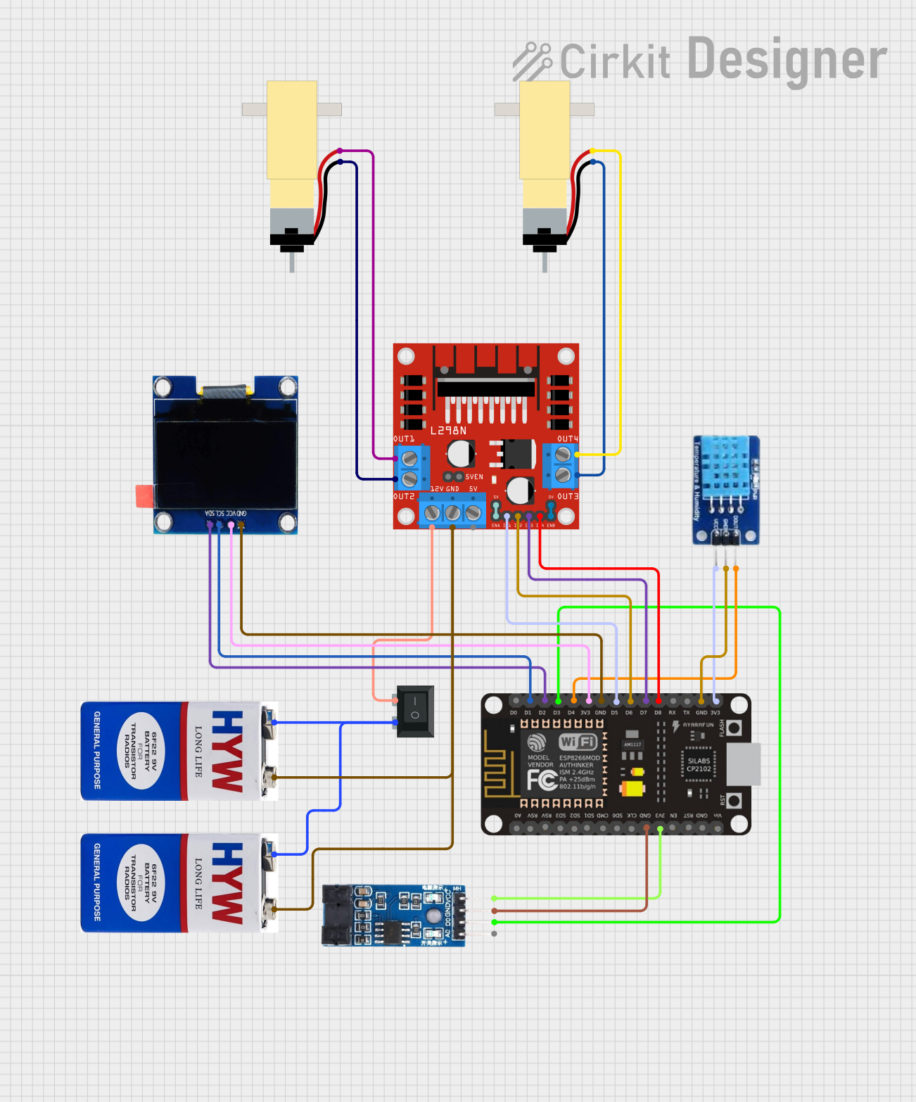
Circuit Documentation
Summary
This circuit is designed to control two hobby gearmotors using an ESP8266 NodeMCU microcontroller and an L298N DC motor driver. The system is powered by two 9V batteries connected in parallel. The ESP8266 NodeMCU interfaces with an OLED display for user feedback, a DHT11 sensor for temperature and humidity readings, and an LM393 comparator for additional input. A rocker switch (SPST) is used to control the power supply to the motor driver. The circuit is likely intended for a small robotic or automation project where motor control and environmental feedback are required.
Component List
Rocker Switch (SPST)
- A single-pole single-throw (SPST) switch used to control the power flow to the motor driver.
ESP8266 NodeMCU
- A microcontroller board with Wi-Fi capability, used as the central processing unit of the circuit.
Hobby Gearmotor with 48:1 Gearbox (x2)
- DC motors with gear reduction, used for driving mechanical parts.
L298N DC Motor Driver
- An H-bridge motor driver capable of driving two DC motors or one stepper motor.
LM393
- A dual differential comparator that provides a digital signal output based on analog input.
DHT11
- A basic, ultra-low-cost digital temperature and humidity sensor.
OLED 1.3"
- A small display used for showing information such as sensor readings or system status.
9V Battery (x2)
- Power sources for the circuit, connected in parallel to increase current capacity without changing the voltage.
Wiring Details
Rocker Switch (SPST)
- Pin 1: Connected to the positive terminal of both 9V batteries.
- Pin 2: Connected to the 12V input of the L298N motor driver.
ESP8266 NodeMCU
- D1 (SCL): Connected to the SCL pin of the OLED display.
- D2 (SDA): Connected to the SDA pin of the OLED display.
- D3: Connected to the D0 pin of the LM393 comparator.
- D4: Connected to the DATA pin of the DHT11 sensor.
- D5, D6, D7, D8: Connected to IN1, IN2, IN3, IN4 of the L298N motor driver respectively.
- 3V3: Connected to the VCC pins of the OLED display, DHT11 sensor, and LM393 comparator.
- GND: Connected to the GND pins of the OLED display, DHT11 sensor, LM393 comparator, and the L298N motor driver.
Hobby Gearmotor with 48:1 Gearbox
- Motor 1:
- Pin 1: Connected to OUT3 of the L298N motor driver.
- Pin 2: Connected to OUT4 of the L298N motor driver.
- Motor 2:
- Pin 1: Connected to OUT1 of the L298N motor driver.
- Pin 2: Connected to OUT2 of the L298N motor driver.
L298N DC Motor Driver
- OUT1, OUT2, OUT3, OUT4: Connected to the respective pins of the two gearmotors.
- 12V: Connected to Pin 2 of the Rocker Switch (SPST).
- GND: Connected to the negative terminal of both 9V batteries.
- ENA, ENB: Connected to +5V-J1 and +5V-J2 respectively for enabling the motor outputs.
LM393
- VCC: Connected to the 3V3 output of the ESP8266 NodeMCU.
- GND: Connected to the GND pin of the ESP8266 NodeMCU.
- D0: Connected to the D3 pin of the ESP8266 NodeMCU.
DHT11
- DATA: Connected to the D4 pin of the ESP8266 NodeMCU.
- VCC: Connected to the 3V3 output of the ESP8266 NodeMCU.
- GND: Connected to the GND pin of the ESP8266 NodeMCU.
OLED 1.3"
- SCL: Connected to the D1 pin of the ESP8266 NodeMCU.
- SDA: Connected to the D2 pin of the ESP8266 NodeMCU.
- VCC: Connected to the 3V3 output of the ESP8266 NodeMCU.
- GND: Connected to the GND pin of the ESP8266 NodeMCU.
9V Batteries
- Positive terminals: Connected to Pin 1 of the Rocker Switch (SPST).
- Negative terminals: Connected to the GND pin of the L298N motor driver.
Documented Code
There is no code provided for the microcontroller. The expected code should initialize and configure the GPIO pins for communication with the OLED display, DHT11 sensor, and LM393 comparator. It should also include routines for controlling the motor driver to operate the gearmotors based on inputs from the comparator or other sensors. Additionally, the code should handle the display of information on the OLED screen and possibly include Wi-Fi functionality for remote monitoring or control, leveraging the capabilities of the ESP8266 NodeMCU.