
Circuit Documentation
Summary of the Circuit
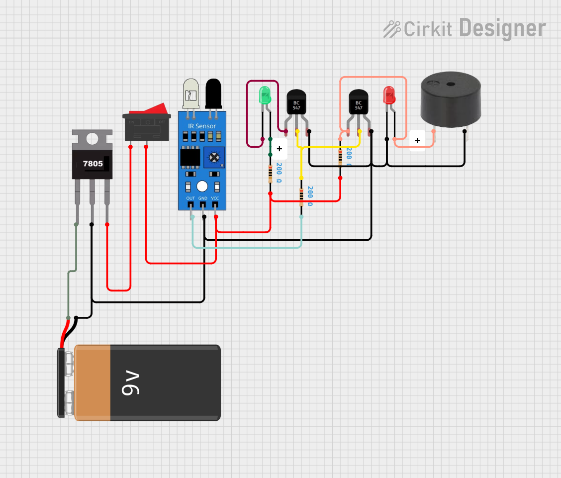
This circuit appears to be a simple control and indication system that uses an IR sensor to detect an event and, in response, activates a red LED and a buzzer. A green LED is also included, which might serve as a status indicator. The circuit is powered by a 9V battery, regulated to 5V by a 7805 voltage regulator. The power to the IR sensor and the rest of the circuit can be controlled by a rocker switch. Two BC547 transistors are used, possibly as switches to control the current flow to the LEDs and the buzzer. Resistors are included to limit the current through the LEDs and to set the base current of the transistors.
Component List
LED: Two Pin (red)
- Description: A red LED used as an indicator.
- Pins: cathode, anode
LED: Two Pin (green)
- Description: A green LED used as an indicator or status light.
- Pins: cathode, anode
9V Battery
- Description: Provides the power source for the circuit.
- Pins: -, +
Rocker Switch
- Description: Controls the power supply to the circuit.
- Pins: 1, 2
IR Sensor
- Description: Detects infrared signals and outputs a digital signal.
- Pins: out, gnd, vcc
Buzzer
- Description: Emits an audible alert when activated.
- Pins: PIN, GND
BC547 Transistor (2 instances)
- Description: NPN transistors used as switches or amplifiers.
- Pins: Collector, Base, Emitter
Resistor (3 instances)
- Description: Limits current or sets voltage levels within the circuit.
- Properties: Resistance: 200 Ohms
7805 Voltage Regulator
- Description: Regulates input voltage to a stable 5V output.
- Pins: Vin, Gnd, Vout
Wiring Details
LED: Two Pin (red)
- Cathode connected to the negative terminal of the 9V battery, IR sensor ground, transistor emitters, buzzer ground, and 7805 ground.
- Anode connected to the collector of one BC547 transistor and the buzzer PIN through a 200 Ohm resistor.
LED: Two Pin (green)
- Cathode connected to the collector of the second BC547 transistor.
- Anode connected to a 200 Ohm resistor.
9V Battery
- Negative terminal (-) connected to the red LED cathode, IR sensor ground, transistor emitters, buzzer ground, and 7805 ground.
- Positive terminal (+) connected to the 7805 voltage regulator Vin pin.
Rocker Switch
- Pin 1 connected to the 7805 voltage regulator Vout pin.
- Pin 2 connected to the IR sensor Vcc, both 200 Ohm resistors connected to the LEDs, and the base of one BC547 transistor through another 200 Ohm resistor.
IR Sensor
- Out pin connected to a 200 Ohm resistor leading to the base of one BC547 transistor.
- Gnd pin connected to the negative terminal of the 9V battery, transistor emitters, buzzer ground, and 7805 ground.
- Vcc pin connected to the rocker switch pin 2.
Buzzer
- PIN connected to the collector of one BC547 transistor and the anode of the red LED through a 200 Ohm resistor.
- GND connected to the negative terminal of the 9V battery, IR sensor ground, transistor emitters, and 7805 ground.
BC547 Transistor
- Collector of the first transistor connected to the anode of the red LED and the buzzer PIN through a 200 Ohm resistor.
- Base of the first transistor connected to the IR sensor out pin through a 200 Ohm resistor.
- Emitter of the first transistor connected to the negative terminal of the 9V battery, IR sensor ground, buzzer ground, and 7805 ground.
- Collector of the second transistor connected to the cathode of the green LED.
- Base of the second transistor connected to the base of the first transistor.
- Emitter of the second transistor connected to the negative terminal of the 9V battery, IR sensor ground, buzzer ground, and 7805 ground.
Resistor
- Three 200 Ohm resistors are used in the circuit:
- One between the IR sensor out pin and the base of the first BC547 transistor.
- One between the anode of the red LED and the collector of the first BC547 transistor.
- One between the anode of the green LED and the rocker switch pin 2.
7805 Voltage Regulator
- Vin pin connected to the positive terminal of the 9V battery.
- Gnd pin connected to the negative terminal of the 9V battery, IR sensor ground, transistor emitters, buzzer ground.
- Vout pin connected to the rocker switch pin 1.
Documented Code
There is no code provided for any microcontrollers in the circuit. If a microcontroller is added to the circuit in the future, the code will be documented in this section.