
Arduino UNO-Based Smart Home Automation System with Bluetooth and Sensor Integration
View and Edit Project In Cirkit Designer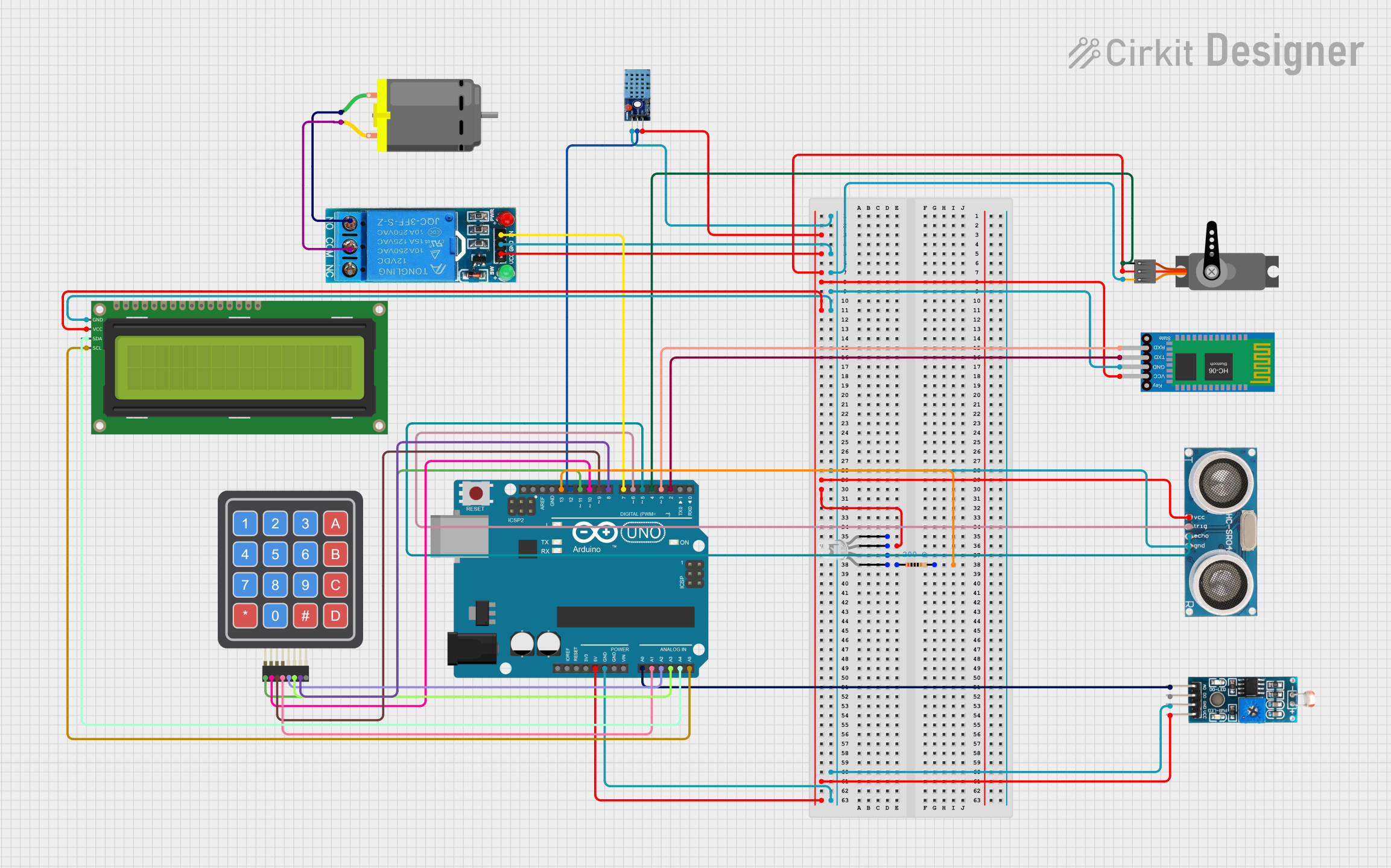
Circuit Documentation
Summary
This circuit is designed to monitor environmental conditions and control various devices based on sensor inputs. It includes an Arduino UNO microcontroller, a DHT11 temperature and humidity sensor, an LDR module, a 12V single-channel relay, a DC motor, a servo motor, a 4x4 keypad, an ultrasonic sensor, a 16x2 I2C LCD, a Bluetooth HC-06 module, and a four-pin LED. The Arduino UNO reads data from the sensors and controls the relay, motor, servo, and LED based on the sensor inputs.
Component List
Arduino UNO
- Description: A microcontroller board based on the ATmega328P.
- Pins: UNUSED, IOREF, Reset, 3.3V, 5V, GND, Vin, A0, A1, A2, A3, A4, A5, SCL, SDA, AREF, D13, D12, D11, D10, D9, D8, D7, D6, D5, D4, D3, D2, D1, D0
DC Motor
- Description: A simple DC motor.
- Pins: pin 1, pin 2
Module LDR
- Description: A light-dependent resistor module.
- Pins: VCC, GND, DO, AO
12V Single Channel Relay
- Description: A relay module for controlling high voltage devices.
- Pins: NC, COM, NO, IN, GND, VCC
Servo
- Description: A servo motor.
- Pins: GND, VCC, PWM
DHT11
- Description: A temperature and humidity sensor.
- Pins: VCC, GND, DATA
LED: Four Pin
- Description: A four-pin LED with red, green, and blue cathodes and a common anode.
- Pins: red cathode, common anode, green cathode, blue cathode
Bluetooth HC-06
- Description: A Bluetooth module for wireless communication.
- Pins: VCC, GND, TXD, RXD
Resistor
- Description: A resistor with a resistance of 200 Ohms.
- Pins: pin1, pin2
Ultrasonic Sensor
- Description: An ultrasonic sensor for distance measurement.
- Pins: +VCC, Trigger, Echo, GND
4x4 Keypad (Simulator)
- Description: A 4x4 matrix keypad.
- Pins: R1, C4, R2, C2, R3, R4, C1, C3
16x2 I2C LCD
- Description: A 16x2 character LCD with I2C interface.
- Pins: GND, VCC, SDA, SCL
Wiring Details
Arduino UNO
- 5V: Connected to VCC of Module LDR, 12V Single Channel Relay, Servo, Bluetooth HC-06, 16x2 I2C LCD, Ultrasonic Sensor, and DHT11.
- GND: Connected to GND of Module LDR, 12V Single Channel Relay, Servo, Bluetooth HC-06, 16x2 I2C LCD, Ultrasonic Sensor, and DHT11.
- A0: Connected to AO of Module LDR.
- A1: Connected to R4 of 4x4 Keypad.
- A2: Connected to C1 of 4x4 Keypad.
- A3: Connected to C2 of 4x4 Keypad.
- A4: Connected to SDA of 16x2 I2C LCD.
- A5: Connected to SCL of 16x2 I2C LCD.
- D13: Connected to pin2 of Resistor.
- D12: Connected to DATA of DHT11.
- D11: Connected to R1 of 4x4 Keypad.
- D10: Connected to R2 of 4x4 Keypad.
- D9: Connected to R3 of 4x4 Keypad.
- D8: Connected to C3 of 4x4 Keypad.
- D7: Connected to IN of 12V Single Channel Relay.
- D6: Connected to Trigger of Ultrasonic Sensor.
- D5: Connected to Echo of Ultrasonic Sensor.
- D4: Connected to GND of Servo.
- D3: Connected to RXD of Bluetooth HC-06.
- D2: Connected to TXD of Bluetooth HC-06.
DC Motor
- pin 1: Connected to NO of 12V Single Channel Relay.
- pin 2: Connected to COM of 12V Single Channel Relay.
Module LDR
- VCC: Connected to 5V of Arduino UNO.
- GND: Connected to GND of Arduino UNO.
- AO: Connected to A0 of Arduino UNO.
12V Single Channel Relay
- VCC: Connected to 5V of Arduino UNO.
- GND: Connected to GND of Arduino UNO.
- IN: Connected to D7 of Arduino UNO.
- NO: Connected to pin 1 of DC Motor.
- COM: Connected to pin 2 of DC Motor.
Servo
- VCC: Connected to 5V of Arduino UNO.
- GND: Connected to GND of Arduino UNO.
- PWM: Connected to PWM of Servo.
DHT11
- VCC: Connected to 5V of Arduino UNO.
- GND: Connected to GND of Arduino UNO.
- DATA: Connected to D12 of Arduino UNO.
LED: Four Pin
- green cathode: Connected to 5V of Arduino UNO.
- red cathode: Connected to pin1 of Resistor.
Bluetooth HC-06
- VCC: Connected to 5V of Arduino UNO.
- GND: Connected to GND of Arduino UNO.
- TXD: Connected to D2 of Arduino UNO.
- RXD: Connected to D3 of Arduino UNO.
Resistor
- pin1: Connected to red cathode of LED: Four Pin.
- pin2: Connected to D13 of Arduino UNO.
Ultrasonic Sensor
- +VCC: Connected to 5V of Arduino UNO.
- GND: Connected to GND of Arduino UNO.
- Trigger: Connected to D6 of Arduino UNO.
- Echo: Connected to D5 of Arduino UNO.
4x4 Keypad (Simulator)
- R1: Connected to D11 of Arduino UNO.
- R2: Connected to D10 of Arduino UNO.
- R3: Connected to D9 of Arduino UNO.
- R4: Connected to A1 of Arduino UNO.
- C1: Connected to A2 of Arduino UNO.
- C2: Connected to A3 of Arduino UNO.
- C3: Connected to D8 of Arduino UNO.
16x2 I2C LCD
- VCC: Connected to 5V of Arduino UNO.
- GND: Connected to GND of Arduino UNO.
- SDA: Connected to A4 of Arduino UNO.
- SCL: Connected to A5 of Arduino UNO.
Documented Code
#include <DHT.h>

// Định nghĩa chân cảm biến và thiết bị
#define PIRPIN 5         // Chân kết nối PIR
#define DHTPIN 12        // Chân dữ liệu DHT
#define DHTTYPE DHT11    // Loại cảm biến DHT11
#define relayPin 8       // Chân điều khiển relay (quạt)
const int ldrPin = A0;   // Chân kết nối LDR
const int redPin = 9;    // Chân LED đỏ
const int greenPin = 10; // Chân LED xanh lá
const int bluePin = 11;  // Chân LED xanh dương

DHT dht(DHTPIN, DHTTYPE);  // Khởi tạo đối tượng DHT
float temperatureThreshold = 30.0;  // Ngưỡng nhiệt độ

void setup() {
  // Cài đặt các chân
  pinMode(PIRPIN, INPUT);
  pinMode(relayPin, OUTPUT);
  pinMode(redPin, OUTPUT);
  pinMode(greenPin, OUTPUT);
  pinMode(bluePin, OUTPUT);

  Serial.begin(9600);  // Khởi động Serial Monitor
  dht.begin();         // Khởi tạo DHT
}

void loop() {
  // Kiểm tra PIR
  int pirState = digitalRead(PIRPIN);
  if (pirState == HIGH) {  // Phát hiện chuyển động
    Serial.println("Phát hiện người! Hoạt động các cảm biến.");

    // Hoạt