
Arduino-Controlled Motion-Activated Relay System with LED Indicator and DC Motor Control
View and Edit Project In Cirkit Designer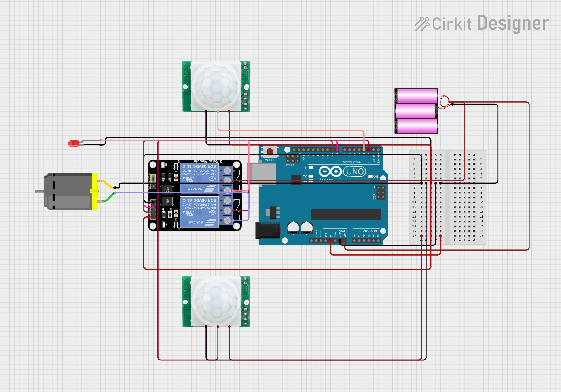
Circuit Documentation
Summary of the Circuit
This circuit is designed to control a DC motor and an LED using an Arduino UNO microcontroller in response to signals from two HC-SR501 motion sensors. The Arduino UNO is powered by a 12V battery, which also supplies power to a 2-channel relay module. The relay module is used to switch the DC motor and the LED on and off. The motion sensors are powered by the 5V output from the Arduino and send signals to the Arduino's digital pins when motion is detected.
Component List
Arduino UNO
- Microcontroller board based on the ATmega328P
- It has 14 digital input/output pins, 6 analog inputs, a 16 MHz quartz crystal, a USB connection, a power jack, an ICSP header, and a reset button.
HC-SR501 Motion Sensor (x2)
- PIR (passive infrared) motion sensor module
- Designed to detect motion through changes in infrared levels emitted by objects.
Relay Module 2 Channel
- A module with two relays that can control high power/high voltage devices.
- Each relay has a normally open (NO) and a normally closed (NC) contact.
LED: Two Pin (red)
- A basic red LED with an anode and cathode for indicating power or status.
DC Motor
- A simple DC motor with two pins for driving mechanical components.
Battery 12V
- A 12V battery providing the main power source for the circuit.
Wiring Details
Arduino UNO
- GND: Connected to the ground plane of the circuit.
- 5V: Supplies power to the HC-SR501 motion sensors and the relay module.
- Vin: Receives power from the 12V battery.
- D9: Controls IN2 on the relay module.
- D8: Controls IN1 on the relay module.
- D3: Receives the OUT signal from one of the HC-SR501 motion sensors.
- D2: Receives the OUT signal from the other HC-SR501 motion sensor.
HC-SR501 Motion Sensor
- GND: Connected to the ground plane of the circuit.
- OUT: Sends a signal to the Arduino UNO when motion is detected.
- VCC: Receives 5V power from the Arduino UNO.
Relay Module 2 Channel
- GND: Connected to the ground plane of the circuit.
- IN1: Controlled by Arduino UNO pin D8.
- IN2: Controlled by Arduino UNO pin D9.
- VCC: Receives 5V power from the Arduino UNO.
- NC1, COM, NO1: Used to control the LED.
- NC2, COM, NO2: Used to control the DC Motor.
LED: Two Pin (red)
- Cathode: Connected to the ground plane of the circuit.
- Anode: Connected to the NO1 contact of the relay module.
DC Motor
- Pin 1: Connected to the NO2 contact of the relay module.
- Pin 2: Connected to the ground plane of the circuit.
Battery 12V
- +: Provides power to the Vin pin of the Arduino UNO and the COM contact of the relay module.
- -: Connected to the ground plane of the circuit.
Documented Code
Arduino UNO Code (sketch.ino)
void setup() {
  // put your setup code here, to run once:

}

void loop() {
  // put your main code here, to run repeatedly:

}
Note: The provided code is a template and does not contain any functional code to control the circuit components. The user is expected to write the necessary code to read the motion sensor outputs and control the relay module accordingly.