ESP32-Based RFID Attendance System with I2C LCD Display

Circuit Documentation
Summary of the Circuit
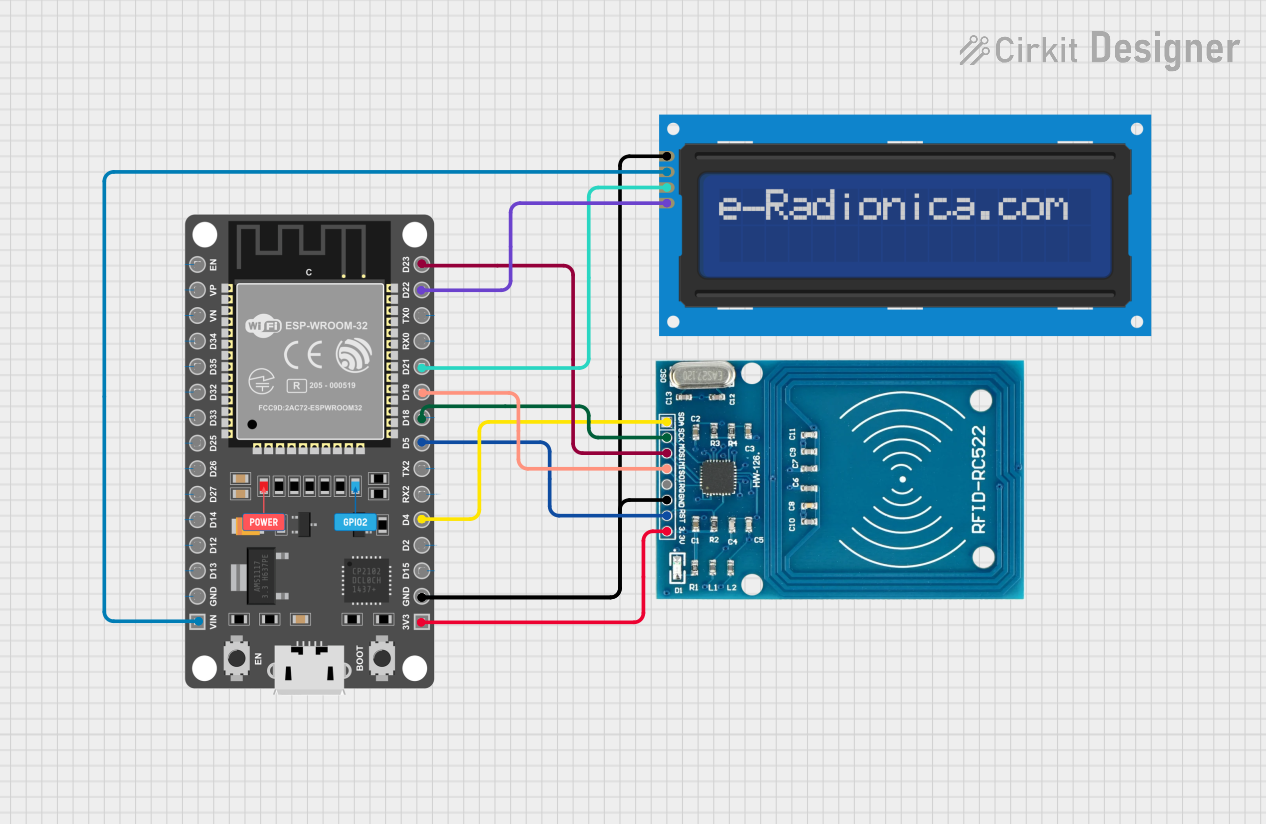
This circuit integrates an ESP32 DEVKIT V1 microcontroller with an RFID-RC522 module and an LCD screen (16x2) with an I2C interface. The ESP32 serves as the central processing unit, controlling the RFID reader for tag scanning and communicating with the LCD screen to display information. The RFID-RC522 is used for reading RFID tags, and the LCD screen displays the tag data or other relevant information. The circuit is designed to operate on a 3.3V power supply for the RFID module and 5V for the LCD, both supplied by the ESP32 DEVKIT V1.
Component List
ESP 32 DEVKIT V1 (30 pins)
- Description: A microcontroller board based on the ESP32 chip, featuring Wi-Fi and Bluetooth connectivity, with a variety of GPIO pins for interfacing with peripherals.
- Pins: EN, VP, VN, D34, D35, D32, D33, D25, D26, D27, D14, D12, D13, GND, VIN, 3V3, D15, D2, D4, RX2, TX2, D5, D18, D19, D21, RX0, TX0, D22, D23
RFID-RC522
- Description: An RFID reader/writer module that operates at 13.56 MHz, commonly used for contactless communication and identification.
- Pins: VCC (3.3V), RST, GND, IRQ, MISO, MOSI, SCK, SDA
LCD screen 16x2 I2C
- Description: A 16x2 character LCD display with an I2C interface for displaying text information.
- Pins: SCL, SDA, VCC, GND
Wiring Details
ESP 32 DEVKIT V1 (30 pins)
- VIN: Connected to the VCC of the LCD screen (16x2 I2C)
- 3V3: Connected to the VCC (3.3V) of the RFID-RC522
- GND: Common ground with the RFID-RC522 and the LCD screen (16x2 I2C)
- D4: Connected to the SDA of the RFID-RC522
- D5: Connected to the RST of the RFID-RC522
- D18: Connected to the SCK of the RFID-RC522
- D19: Connected to the MISO of the RFID-RC522
- D21: Connected to the SDA of the LCD screen (16x2 I2C)
- D22: Connected to the SCL of the LCD screen (16x2 I2C)
- D23: Connected to the MOSI of the RFID-RC522
RFID-RC522
- VCC (3.3V): Powered by the 3V3 pin of the ESP 32 DEVKIT V1
- RST: Connected to the D5 of the ESP 32 DEVKIT V1
- GND: Common ground with the ESP 32 DEVKIT V1 and the LCD screen (16x2 I2C)
- SDA: Connected to the D4 of the ESP 32 DEVKIT V1
- SCK: Connected to the D18 of the ESP 32 DEVKIT V1
- MISO: Connected to the D19 of the ESP 32 DEVKIT V1
- MOSI: Connected to the D23 of the ESP 32 DEVKIT V1
LCD screen 16x2 I2C
- VCC: Powered by the VIN pin of the ESP 32 DEVKIT V1
- GND: Common ground with the ESP 32 DEVKIT V1 and the RFID-RC522
- SDA: Connected to the D21 of the ESP 32 DEVKIT V1
- SCL: Connected to the D22 of the ESP 32 DEVKIT V1
Documented Code
No code was provided for the microcontrollers in the circuit. To fully utilize the circuit's capabilities, embedded code for the ESP32 DEVKIT V1 should be written to handle communication with the RFID-RC522 module and the LCD screen. The code should initialize the peripherals, handle the RFID reading process, and display the results on the LCD screen. Since no code is available, this section cannot be completed at this time.