
ESP32-Controlled Autonomous Robot with GPS and Ultrasonic Sensors
View and Edit Project In Cirkit Designer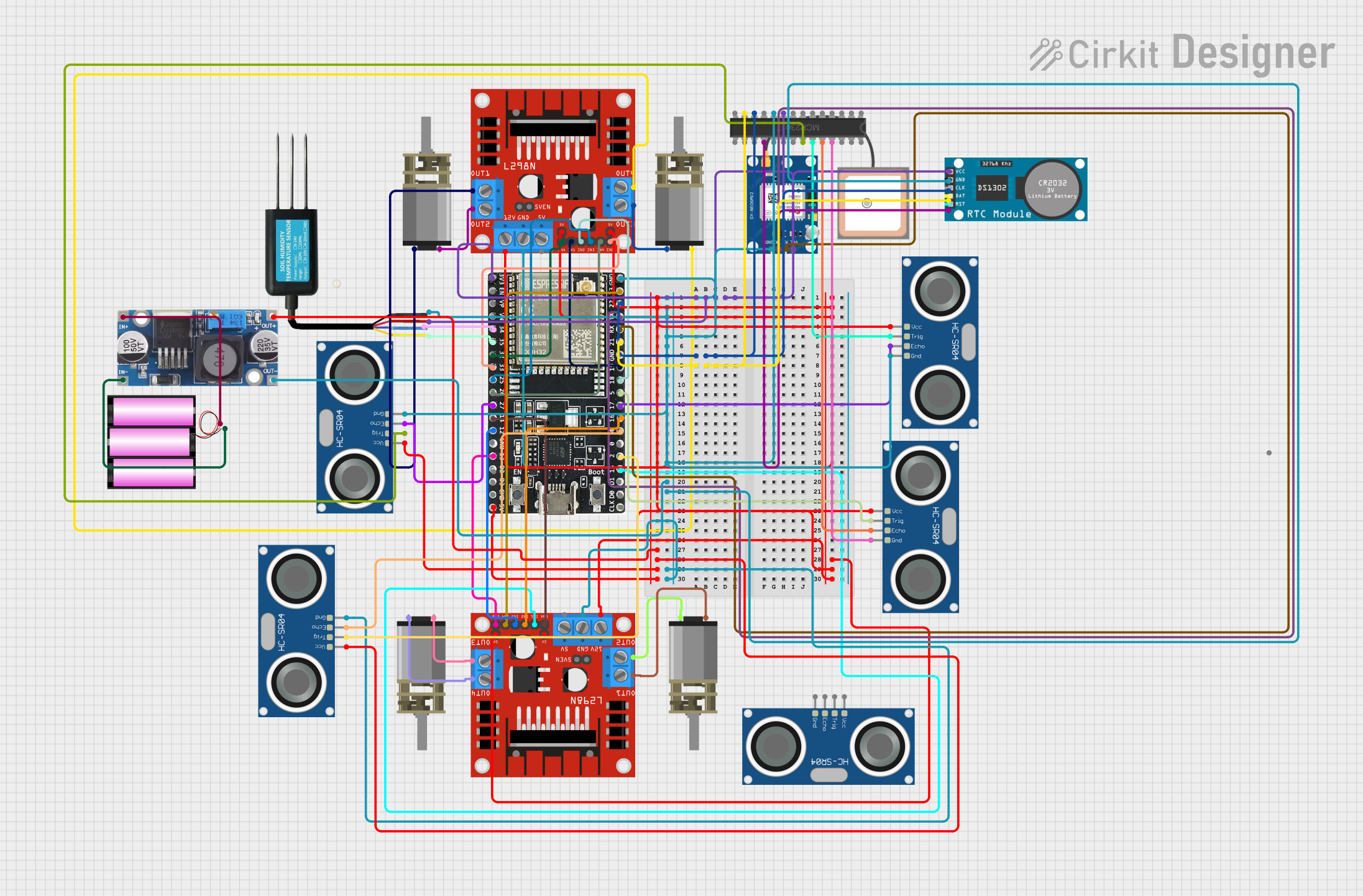
Circuit Documentation
Summary
This circuit is designed to control multiple DC Mini Metal Gear Motors using L298N DC motor drivers, interfaced with an ESP32-WROOM-32UE microcontroller. The circuit also includes a variety of sensors such as Soil Moisture Sensor, GPS NEO 6M, and multiple HC-SR04 Ultrasonic Sensors. A MCP23017 I/O expander is used to increase the number of I/O pins available to the ESP32. The circuit is powered by a 12V battery, with a Step down Buck converter to provide the necessary voltage levels to the components. The ESP32 handles the logic and sensor data processing, while the motor drivers control the motors based on the commands from the ESP32.
Component List
- DC Mini Metal Gear Motor: A compact and powerful motor suitable for driving small robots or mechanical parts.
- L298N DC Motor Driver: A module capable of driving up to two DC motors with control over speed and direction.
- ESP32-WROOM-32UE: A powerful microcontroller with Wi-Fi and Bluetooth capabilities, suitable for a wide range of IoT applications.
- Soil Moisture Sensor: A sensor that measures the moisture level in the soil, useful for agricultural or gardening applications.
- GPS NEO 6M: A GPS module that provides location data.
- HC-SR04 Ultrasonic Sensor: A sensor that measures distance using ultrasonic waves.
- MCP23017: A 16-bit I/O expander with I2C interface to increase the number of I/O pins available to the microcontroller.
- RTC (Real Time Clock): A module that keeps track of the current time and date.
- Step down Buck Converter: A power supply module that steps down voltage from a higher level to a lower level.
- Battery 12V: A 12V battery that provides power to the circuit.
Wiring Details
DC Mini Metal Gear Motor
- IN1 and IN2: Connected to the corresponding OUT pins on the L298N DC motor driver to control the motor's direction and speed.
L298N DC Motor Driver
- OUT1, OUT2, OUT3, OUT4: Connected to the IN pins of the DC Mini Metal Gear Motors.
- 12V: Connected to the 12V battery.
- GND: Common ground with the ESP32 and other components.
- 5V: Connected to the 5V output from the Step down Buck Converter.
- ENA, ENB: Connected to the ESP32 for enabling the motor driver.
- IN1, IN2, IN3, IN4: Connected to the ESP32 for controlling motor direction.
ESP32-WROOM-32UE
- 3v3: Connected to the 3.3V power supply net.
- GND: Connected to the common ground net.
- Digital and Analog Pins: Connected to various components such as the L298N motor driver, sensors, and MCP23017 for control and data acquisition.
Soil Moisture Sensor
- VCC: Connected to the 3.3V power supply net.
- GND: Connected to the common ground net.
- RS485 - A/B: Connected to the ESP32 for data communication.
GPS NEO 6M
- VCC: Connected to the 3.3V power supply net.
- GND: Connected to the common ground net.
- TX, RX: Connected to the ESP32 for data communication.
HC-SR04 Ultrasonic Sensor
- VCC: Connected to the 5V power supply net.
- GND: Connected to the common ground net.
- TRIG: Connected to the ESP32 or MCP23017 for triggering the distance measurement.
- ECHO: Connected to the ESP32 or MCP23017 for receiving the distance measurement.
MCP23017
- VDD: Connected to the 3.3V power supply net.
- VSS: Connected to the common ground net.
- SDA, SCL: Connected to the ESP32 for I2C communication.
- RESET: Connected to the RTC for reset functionality.
- GPA/GPB Pins: Connected to various sensors for expanding the I/O capabilities.
RTC
- VCC: Connected to the 3.3V power supply net.
- GND: Connected to the common ground net.
- CLK, DAT, RST: Connected to the ESP32 for timekeeping and data communication.
Step down Buck Converter
- IN +: Connected to the 12V battery positive terminal.
- IN - GND: Connected to the 12V battery negative terminal.
- OUT +: Connected to the 5V power supply net.
- OUT - GND: Connected to the common ground net.
Battery 12V
- +: Connected to the Step down Buck Converter and the L298N motor driver.
- -: Connected to the common ground net.
Documented Code
ESP32-WROOM-32UE Microcontroller Code (sketch.ino)
void setup() {
  // put your setup code here, to run once:

}

void loop() {
  // put your main code here, to run repeatedly:

}
This code is a template for the ESP32 microcontroller. The setup() function is called once when the microcontroller is powered on or reset. It is used to initialize the pins and set up the communication protocols. The loop() function is called repeatedly and contains the main logic of the program. It is where the microcontroller reads sensor data, controls the motors, and communicates with other devices.
The actual implementation details would be added to the setup() and loop() functions based on the specific requirements of the circuit's operation. This would include configuring the I2C communication for the MCP23017 and RTC, setting up the serial communication for the GPS module, initializing the motor driver control pins, and writing the logic for reading the sensors and controlling the motors.