
Arduino Nano-Controlled Obstacle Avoidance Robot with IR and Ultrasonic Sensors
View and Edit Project In Cirkit Designer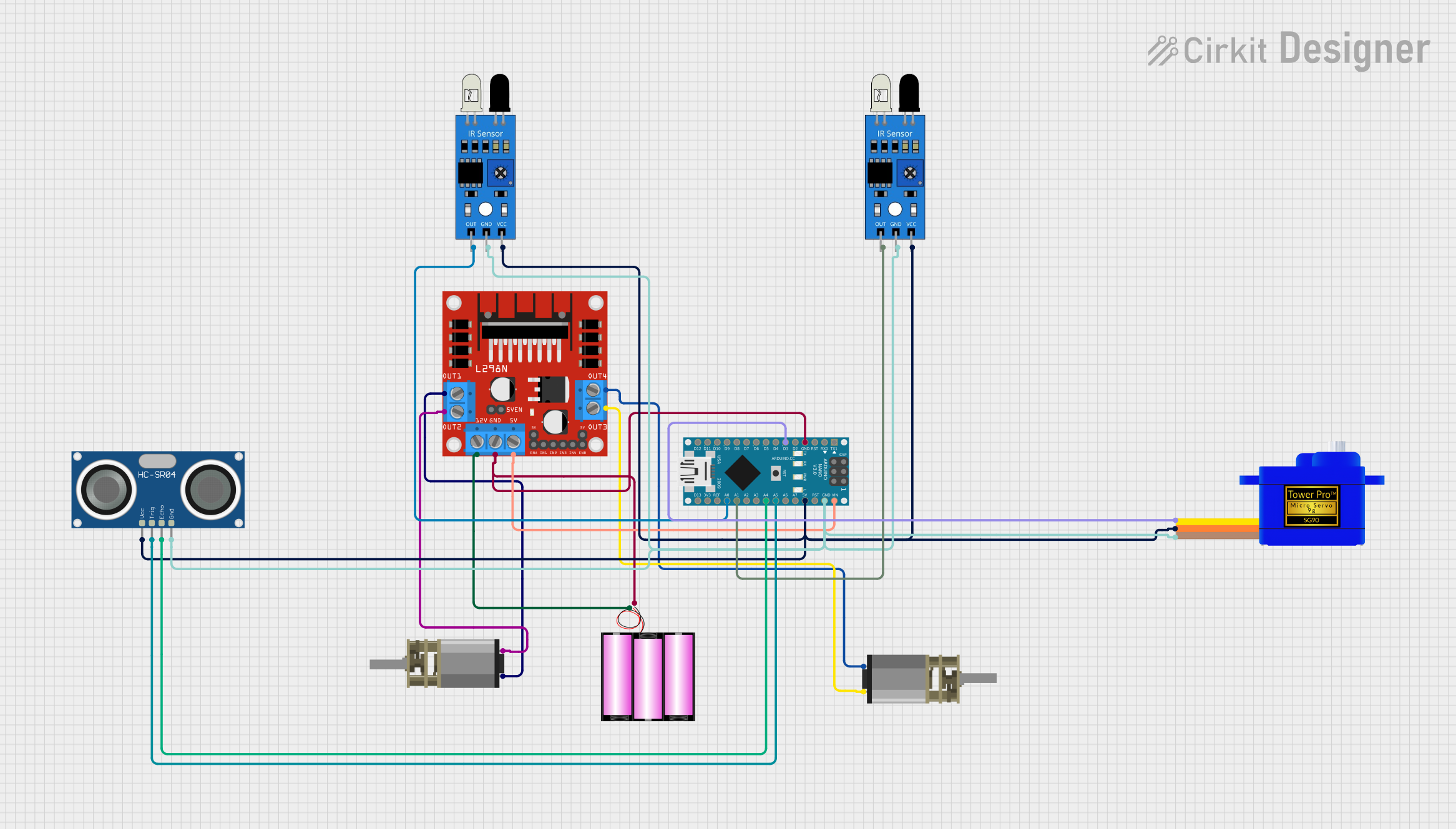
Circuit Documentation
Summary
This circuit integrates various sensors, actuators, and a microcontroller to form a system capable of sensing and actuation. The core of the circuit is an Arduino Nano, which interfaces with IR sensors, a DC motor driver, a servomotor, and an ultrasonic sensor. The DC motor driver controls two DC Mini Metal Gear Motors, and the system is powered by a 12V battery. The IR sensors are used for detecting proximity or measuring the intensity of IR light, while the ultrasonic sensor is used for distance measurement. The servomotor is controlled by the Arduino Nano for precise angular movement. The circuit is designed to be modular, with the ability to expand or modify based on the requirements of the application.
Component List
IR Sensor
- Pins: out, gnd, vcc
- Description: An infrared sensor capable of detecting proximity or measuring IR light intensity.
DC Mini Metal Gear Motor
- Pins: IN1, IN2
- Description: A compact DC motor with a gearbox for increased torque.
Arduino Nano
- Pins: D1/TX, D0/RX, RESET, GND, D2, D3, D4, D5, D6, D7, D8, D9, D10, D11/MOSI, D12/MISO, VIN, 5V, A7, A6, A5, A4, A3, A2, A1, A0, AREF, 3V3, D13/SCK
- Description: A small, complete, and breadboard-friendly board based on the ATmega328 (Arduino Nano 3.x).
Servomotor SG90
- Pins: SIG, VCC, GND
- Description: A small and lightweight servo for RC vehicles, helicopters, and drones.
HC-SR04 Ultrasonic Sensor
- Pins: VCC, TRIG, ECHO, GND
- Description: An ultrasonic ranging module that provides 2cm to 400cm non-contact measurement functionality.
L298N DC Motor Driver
- Pins: OUT1, OUT2, 12V, GND, 5V, OUT3, OUT4, 5V-ENA-JMP-I, 5V-ENA-JMP-O, +5V-J1, +5V-J2, ENA, IN1, IN2, IN3, IN4, ENB
- Description: A high-power motor driver capable of driving up to 4 DC motors or 2 stepper motors.
Battery 12V
- Pins: +, -
- Description: A 12V power source for the circuit.
Wiring Details
IR Sensor
- out: Connected to Arduino Nano A0 or A1 for analog signal input.
- gnd: Connected to the common ground.
- vcc: Connected to the 5V output from the Arduino Nano.
DC Mini Metal Gear Motor
- IN1 and IN2: Connected to the L298N DC motor driver OUT1, OUT2, OUT3, and OUT4 for motor control.
Arduino Nano
- GND: Common ground for the circuit.
- 5V: Provides power to IR sensors, servomotor, and ultrasonic sensor.
- A0, A1: Analog inputs connected to IR sensors.
- D3: Digital output connected to the servomotor SG90 signal pin.
- VIN: Connected to the L298N DC motor driver 5V input for power.
- A4, A5: Connected to HC-SR04 ultrasonic sensor ECHO and TRIG pins for distance measurement.
Servomotor SG90
- SIG: Connected to Arduino Nano D3 for control signal.
- VCC: Connected to 5V power from the Arduino Nano.
- GND: Connected to the common ground.
HC-SR04 Ultrasonic Sensor
- VCC: Connected to 5V power from the Arduino Nano.
- TRIG: Connected to Arduino Nano A5 for triggering distance measurement.
- ECHO: Connected to Arduino Nano A4 for receiving the distance measurement signal.
- GND: Connected to the common ground.
L298N DC Motor Driver
- OUT1, OUT2, OUT3, OUT4: Connected to DC Mini Metal Gear Motors.
- GND: Common ground for the circuit.
- 5V: Powered by the Arduino Nano VIN pin.
- 12V: Powered by the 12V battery.
Battery 12V
- + (positive): Connected to the L298N DC motor driver 12V input.
- - (negative): Connected to the common ground.
Documented Code
Arduino Nano Code (sketch.ino)
void setup() {
  // put your setup code here, to run once:

}

void loop() {
  // put your main code here, to run repeatedly:

}
Note: The provided code is a template and does not contain any functional code. It needs to be populated with the logic to control the sensors, motors, and other components based on the specific requirements of the application.